


For parts or assistance, call Simer Customer Service at 1-800-468-7867 / 1-800-546-7867
Installation / Operation 3
DESCRIPTION
This non-corrosive pump pumps up to 1380 GPH,
pumps floors dry to 3/16”, fits inside a 6” opening, and
weighs only 9 pounds. Includes a 1-1/4” garden hose
adapter and 10’ replaceable DC cable leads.
Fire and Explosion Hazard. Do not use in
explosive atmospheres. Use only in a vented atmos-
phere. Protect the motor from explosive fumes. Pump
water only with this pump.
NOTICE: Do not use a battery charger to power this
pump.
For more information, see your retailer, or call Simer
customer service at 1-800-468-7867.
SPECIFICATIONS
Liquid Temp. Range ........... 35° to 120° F (1.7° to 50° C)
Circuit Requirement ...................................12 Volts DC
NOTICE: Pump water only with this pump. Never run
the pump dry!
PERFORMANCE
INSTALLATION
1. Power Supply: Pump must be used only with a 12
Volt DC battery, or a direct current power supply. Do
not connect to 120VAC.
2. Place the pump in the water on a hard surface.
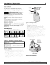
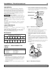
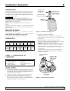
3. Install a check valve between the pump discharge
port and the discharge hose adapter to prevent back-
ward flow through the pump when the pump shuts
off. See Figure 1.
4. Connect the discharge hose.
NOTICE: Do not allow the pump to sit in dirt or
sand. This will cause rapid wear of the pump.
5. Be sure the discharge line is open.
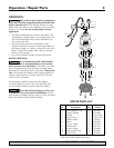
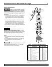
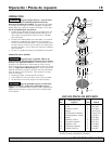
6. Connect the motor lead wires as indicated in Table I
and as shown in Figure 2.
NOTICE: One of two cordsets is supplied with the
pump. To determine which wire is negative and
which is positive, refer to the wire labels. Fuse in on
the positive wire. Wire color does not matter.
In order for the pump to run in the proper direction
and prevent harm to the pump, the wires must be
connected correctly.
GPM (LPM) AT TOTAL FEET (M)
Model 0 5 10 15 20 25 30
No. (0) (1.5m) (3m) (4.6m) (6.1m) (7.6m) (9.1m)
CAPACITY GALLONS(L)/Minute
23 20 18 14 10 6 1
P3010
(87) (76) (68) (53) (38) (23) (3.8)
Cord connector,
wiring, and
handle are
removed
for clarity.
1-1/4"
Discharge
Hose Adapter
Check
Valve
(Sold Separately)
Discharge
Port
Figure 1 – Discharge assembly.
Motor Lead Wires
Connect the
negative wire
to the negative
battery terminal.
Connect the
positive wire,
with the fuse,
to the positive
battery terminal.
®
Figure 2 – Wiring Connections.
Connect the ... To the ...
1. Connector with Positive (+) battery terminal
positive (+) wire
2. Connector with Negative (-) battery terminal
negative (-) wire
TABLE I – WIRING CONNECTIONS
Performance depends on state of battery.