


Installation 5
For parts or assistance, call Simer Customer Service at 1-800-468-7867
NOTE: Installation of a low pressure safety cutoff
switch on the pump discharge is recommended (and
may be required by your local code) to shut off the
power in case of low discharge pressure (caused by
broken pipe, etc.).
2. Mount the pump on a solid base in the location you
have decided on.
3. Choose a time that will allow you to shut off the
water to the household while you install the Ace-In-
The-Hole Automatic Booster Pump.
4. Shutoff the main water supply valve to the household.
5. Open any faucet to relieve water pressure in the
plumbing. Once the water pressure is relieved, close
the faucet.
6. READ STEP 6 COMPLETELY BEFORE STARTING TO
WORK ON IT. You must remove a length of pipe
from the main water supply line to allow installation
of elbows for the Ace-In-The-Hole Automatic Booster
Pump. The locations of the cuts must take into con-
sideration the size of the elbows being used, the
length of the threads in threaded joints or the overlap
in glued or soldered joints, etc.. Position the elbows
in line with the pump suction and discharge threads.
There may be some water leakage while cutting the
pipe. Remove any burrs or shavings caused by the
cutting tool.
NOTE: Galvanized pipe may not need to be cut.
If there is a union close to the pump location, dis-
assemble the union and remove (unscrew) pipe back
past the pump location. Have new lengths of pipe cut
and threaded to allow for the pump installation.
NOTE: Both female suction and male discharge ports
have 1” NPT threads. Depending on your type of
connection and the size of your home’s piping, you
may need to install adapters on the ports.
7. Once the short piece of pipe is removed, the piping
above the cut can be drained to prevent water mess.
Place a pail under the opening going to the house-
hold. Open the highest faucet in the system to let in
air so the water can fall out of the pipes into the pail.
Once it’s drained, close the faucet.
8. Install the elbows in the main water supply line. Point
them toward the pump.
Risk of burst hose and flooding. Do not
install with flexible hoses. Use only rigid piping that
meets code.
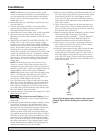
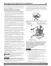
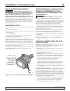
9. Install piping from elbows to pump including a union
in each line, an elbow in the discharge line, and a
check valve in the pump suction line. The arrow on
the check valve must point to the pump suction (see
Figure 2). If not already in the plumbing system,
install a pressure relief valve in the pump discharge
line capable of passing the full pump flow at 100 psi
(689 kPa). If local code requires installation of a pres-
sure relief valve capable of handling the full pump
flow at a pressure less than 100 psi (689 kPa), follow
the code requirements. A low pressure safety cutoff
switch should also be installed in the discharge line,
and may be required by your local codes.
10.With all pipe and fittings installed and sealed, turn on
the main water supply slowly to pressurize the system
and check for leaks. If any leaks appear, turn the
main valve off, open a faucet to relieve the pressure,
and repair the leak. Repeat this step until there are no
leaks in the system.
11. Open a faucet to release the air from the pipes and
allow water to flow. When a steady stream of water
flows out of the faucet, the pump is full of water and
fully primed. Close the faucet.
12.Before continuing with the installation, see the sections
of this manual titled “Electrical Connections”,
“Automatic Pressure Controller”, “Normal Operation”,
and “When Does The Pump Stop Operating” for
detailed information on how the system functions.
13.At this point, you can plug in the pump for the first
time. When you plug in the power cord, the pump
will start and run for a few seconds.
14.When the pump stops running (after it shuts off auto-
matically), the system is at the boosted pressures.
Inspect the pipe and fittings again for water leaks. If
any leaks appear, unplug the pump, turn the water
main valve off, open a faucet to relieve the pressure
and repair the leak. Repeat this step until there are no
leaks in the system.
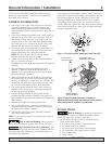
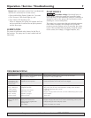
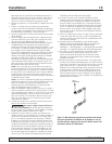
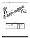
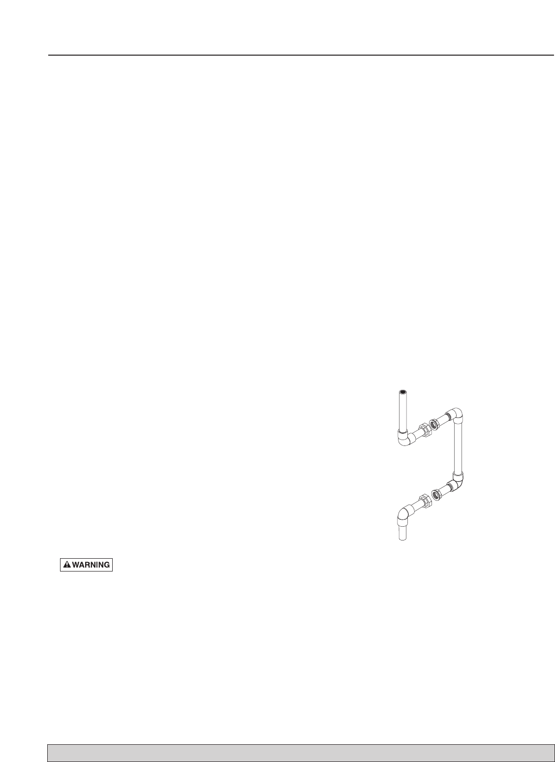
Water
Supply In
To
Household
5601 0807
Figure 3:Typical bypass piping needed to allow removal of
pump for repair without shutting down household water
system.