


Page 22
ProMinent
®
Dulcodes UV-Desinfektionsanlage
Product description S2Ba/S2Ca
Technical data
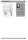
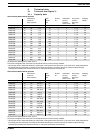
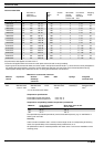
Corresponding to the type of pump, overflow valves are available for pressure stages p
nom
4, 7,
10, 12 and 16 bar with (1.05 ... 1.15) xp
nom
opening pressure.
Material in contact with metered medium
Material Liquid end Suction/ Seals Balls Springs Integrated
version discharge overload
connector valve
PVT PVDF PVDF PTFE Ceramic / glass* Hastelloy C PDFE/Viton
®
SST Stainless steel Stainless steel PTFE Stainless steel Hastelloy C Stainless steel/
1.4571/1.4404 1.4581 1.4404 Viton
®
*for 07120, 07220, 04350
Viton
®
is a registered trademark of DuPont Dow Elastomers.
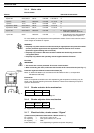
Use for intended purpose/Use unintended purpose
Use for intended purpose
Protect the dosing pump against unacceptable high overpressure produced by the dosing pump.
Use the overflow value only in connection with liquid with a viscosity of up to max. 200 mPa s.
IMPORTANT
• The ceramic ball and ball seat of the overflow valve are wearing parts. Slight leakage can
occur at the safety valve after a prolonged period of operation. The ball and ball seat
should be replaced if leaks occur.
• The bypass line must always be connected and must be routed back into the supply tank.
Use for unintended purpose
To protect the system from impermissible overpressure.
The pump must not be operated without the bypass line connected.
The bypass line must not be connected in the intake line (the bleeder function will no longer be
guaranteed). The bypass line must be routed back into the supply tank.
WARNING
When carrying out maintenance work on the overcurrent valve, pay attention to the
tensioned state of the pressure spring item132! Wear safety goggles!
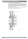
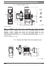
2.2.6 Diaphragm rupture sensor
Function:
Monitors the seals in the working diaphragm. This liquid end can continue to function for a short
period in emergency mode, i.e. full operating pressure, no leakage, even after diaphragm rupture.
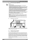
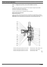
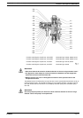
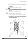
Design and function description (see Fig. 8)
Liquid ends with diaphragm rupture sensors comprise a standard liquid end (item 100) a working
diaphragm (item 200) and an auxiliary diaphragm (item 148) The auxiliary diaphragm is positioned
between the back plate (item 201) and the interim plate (item 147) and forms a sealed
compartment together with the working membrane (item 200).
The leak tightness of the working diaphragm, Item 200, is monitored with a diaphragm failure
detector, Item 104, that triggers a contact signal in the event of diaphragm failure so that the
pump is stopped in the S2Ca and the diaphragm failure is indicated on a LCD.