


5
PLUMBING
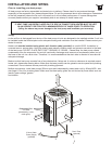
Alto heat pumps are supplied with 1.5" BSP parallel threads, male. We
strongly recommend a 1.5" female socket union is applied to
inlet/outlets for future draining and servicing of the appliance.
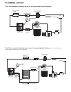
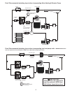
Alto heat pumps must be installed in the return line after the filter. If an
existing heater or back-up heater has been installed then the heat pump
should be installed between the filter and the other heater. If solar
heating has been installed, the heat pump should be installed after the solar heating system. See Drw.2 page7.
If the heat pump is to be installed at a lower level than the pool then isolation valves or non-return valves should be
installed.
Do not route any plumbing lines across heater inlet panels. All plumbing should be adequately supported.
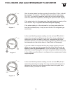
Once all plumbing connections have been completed the filtration should be turned on and the systems tested for
leaks. A refrigerant/flow meter is located next to the control panel. Alto heat pumps will generally take the full flow
of the filtration pump. In some instances if there is too much flow (see page 12 re refrigerant/ flow meter) a by-pass
may be required. If there is insufficient flow an auxiliary booster pump may be required. Please contact your dealer
for advice.
Important - (applicable for stainless steel/copper heat exchangers) Standard unit. If your pool has an automatic
chemical dosing appliance the heat pump should be installed prior to the dosing system. See applicable drawings
(1-4) on pages 7-8.
2 x1.5” Female/Threaded
Socket Unions Required
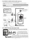
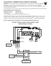
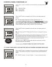
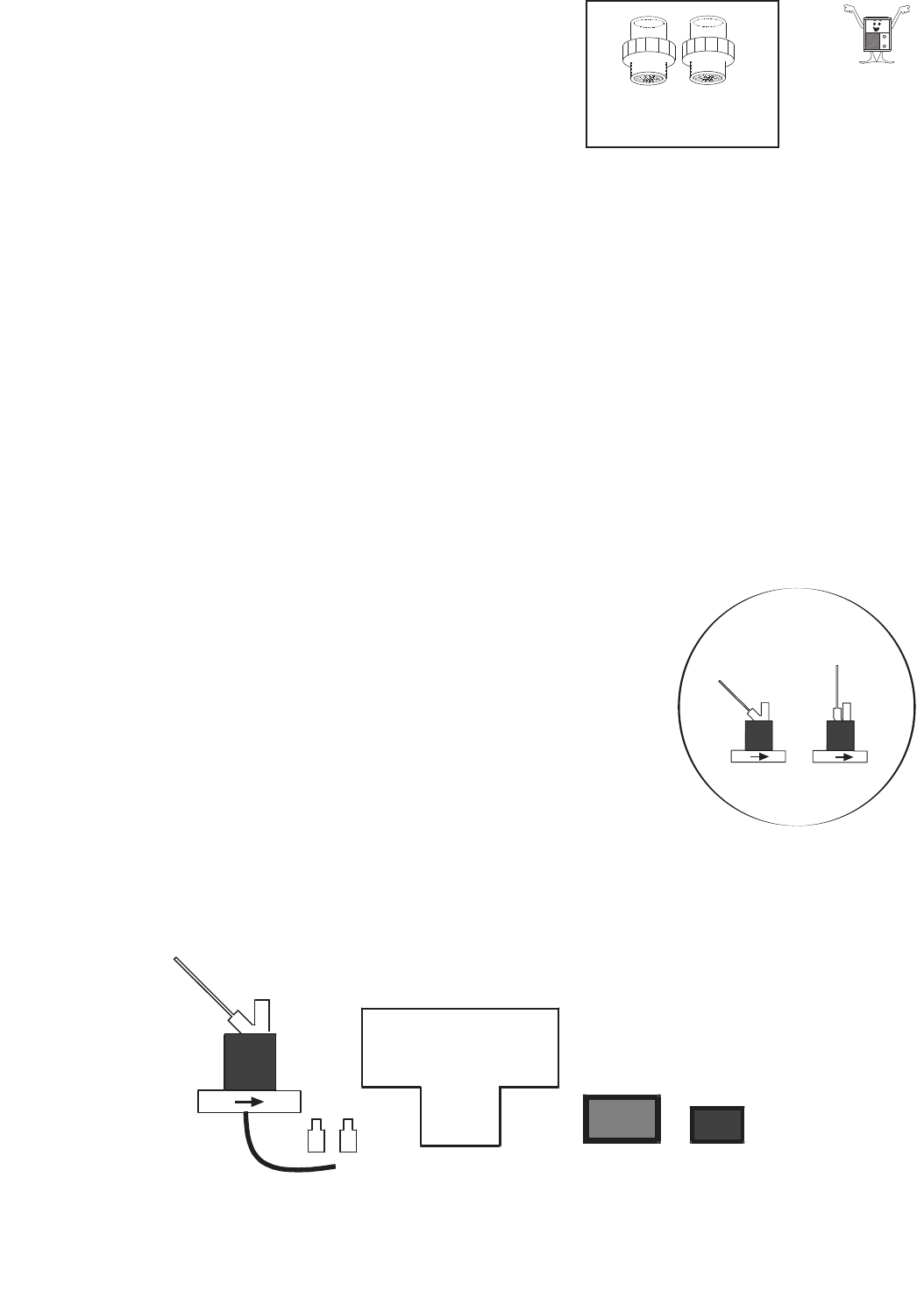
FLOW SWITCH (Optional)
Alto heat pumps have the option of installing a flow switch. A flow switch will deactivate the heater if there is a loss
of water flow i.e. in the event that the circulation pump deprimes (no flow) the heater
will switch off.
We recommend that the heat pump should be interlock wired with the
circulation pump i.e. heat pump only functions when pool circulation pump is
running. A flow switch (provided) can also be installed as an extra precaution in
the event that there is a loss of water flow (i.e. circulation pump deprimes).
It is our recommendation that the flow switch is installed for added protection
on a pool installation that is below ground. If the heater is to be installed on an
above ground pool, the circulation pump is normally under flooded suction
therefore, heater and filtration pump could be wired together.
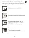
In the event that there is no flow ‘E3’ will be displayed on the control panel and
heater will stop functioning.
ELECTRICIAN NOTE - PLEASE CHECK CONTINUITY OF FLOW SWITCH BEFORE INSTALLING.
PLEASE ALSO SEE PAGE 15 - FILTRATION & FAQ
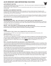
OFF
ON
1 X FLOW SWITCH
1 X CRIMP -ON CONNECTIONS
1 X 1.5”- 0.75” PLN RED. BUSH
1 X 0.75” PLAIN - 0.5” FEMALE THR. RED. BUSH