


5061 Brooks St. Montclair, CA 91763
800-527-4790 Fax 1-909-399-3357
www.sierraproductsinc.com
P/N EF3801 4001 Sensor replacment 4/04
2 6
EF3801/4001 V1 Feed System
Service or Repair Instruction
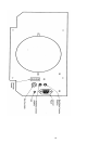
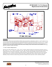
Figure 1
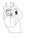
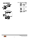
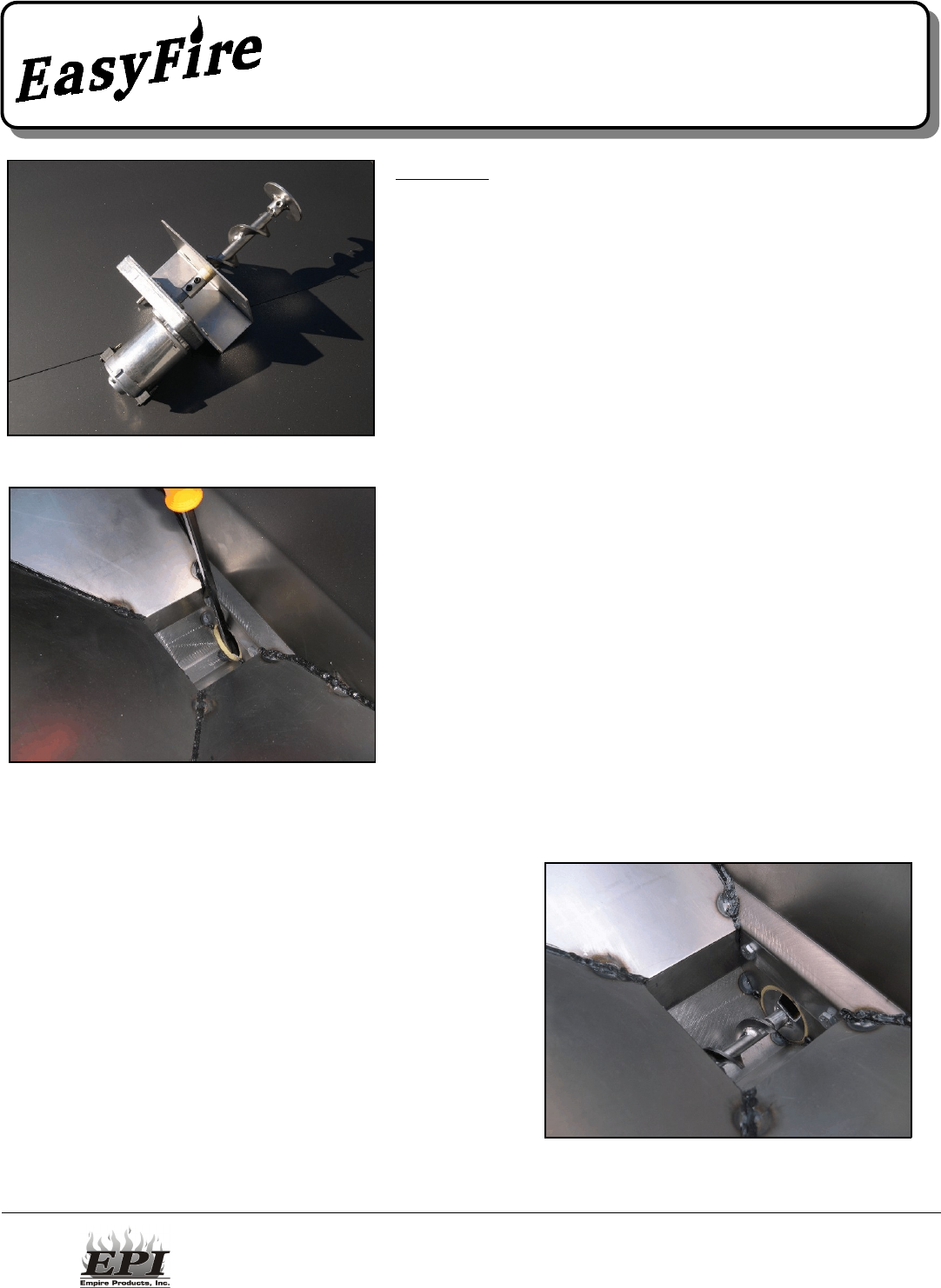
Figure 3
OVERVIEW
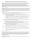
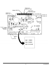
The EasyFire feed system consists of four main components, feed
motor and mounting plate, feed auger shaft, feed disk, and feed disk
bushing (Figure 1). These components are designed to provide
thousands of hours of service and rarely require service or
replacement. Operation of feed system is controlled by the main
control board based on the stoves temperature and heat setting. Unlike
other pellet stoves, the system operates by increasing and decreasing
the speed of the auger and disk. Pellets are pushed forward toward the
disk and as the disk rotates clockwise (from front of stove) allows the
pellets to be feed into the shoot. Three feed disk sizes are available
with the standard = 1, medium = 2, and large = 3. #3 feed disks are for
large or long pellets only. If overfeeding or under-feeding is a problem
and adjusting the feed trim will not compensate, changing the feed disk
is advised.
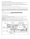
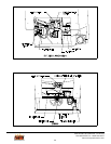
Removing and Replacing the Feed Assembly: The feed assembly
and gear motor is accessed by removing the rear inspection panel for
both the heater and insert. Remove the four or six #8 screws
attaching the inspection cover and remove cover. Remove all pellets
from hopper and feed disk area inside unit. Locate feed motor and
unplug wire harness connections (note location of red banded wire on
motor to assure proper rotation of motor). Remove wing nuts (or #10
nuts on some units) attaching feed motor bracket to rear of feed shoot.
Gently remove feed assembly by pulling toward the rear of unit. The
feed shaft maybe removed by loosening the allen screws holding the
shaft coupler. Remove the two #8 phillips screws holding the feed
motor bracket to the gear motor. Reverse process to install feed
motor assembly.
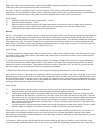
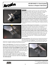
Bushing replacement: Disk bushing may be replaced by removing 2-
#8 retaining screws and carefully prying with a large flat blade screw
driver from inside hopper (Figure 2). To re-install bushing clean area
with thinner or alcohol and apply a small amount of red lock-tight to bushing. Align with plate and carefully pry back with
screw driver. Straighten bushing and install retaining screws.
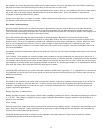
Shaft or Disk Replacement: The feed disk and shaft depth are set
at the factory to allow the feed disk to ride fully in the feed disk
bushing. When replacing either component, make sure the installed
disk ride toward the rear of the disk (Figure 3) and does not extend
to far forward. If the disk is set to far forward it may jamb causing
the shaft to bend or break. Assemble the new components onto the
motor drive loosely then install into stove. Carefully position disk and
mark or tighten disk onto shaft. Remove disk and motor assembly
from stove and tighten with 1/8" allen wrench.
NOTE: WHEN ASSEMBLING THE SHAFT AND COUPLER,
ALWAYS USE A SMALL AMOUNT OF LOCK TIGHT (RED) ON
ALLEN SET SCREWS. AFTER THE ASSEMBLY HAS BEEN
INSTALLED THE FEED DISK MUST RIDE IN THE CENTER OF
THE FEED BUSHING.