


3. Newlabelsforrightside-upapplicationonoutsideofblower
compartmentdoormaybepurchasedinakitfromyourdistrib-
utortocoverupside-downlabels.
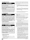
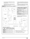
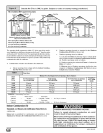
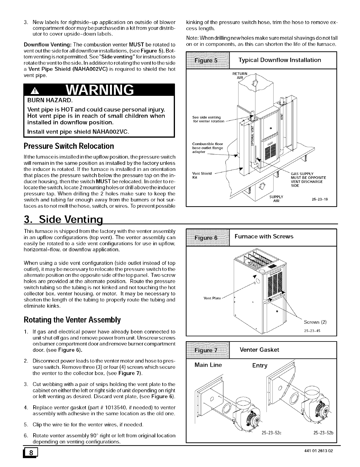
DownflowVenting:ThecombustionventerMUSTberotatedto
ventoutthesideforalldownflowinstallations,(seeFigure5).Bot-
tomventingisnotpermitted.See"Sideventing"forinstructionsto
rotatetheventtotheside.Inadditiontorotatingtheventtotheside
aVentPipeShield(NAHAOO2VC)isrequiredtoshieldthehot
ventpipe.
BURN HAZARD.
Vent pipe is HOT and could cause personal injury.
Hot vent pipe is in reach of small children when
installed in downflow position.
Install vent pipe shield NAHA002VC.
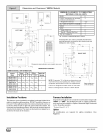
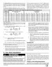
Pressure Switch Relocation
If the furnace is installed in the upflow position, the pressure switch
will remain in the same position as installed by the factory unless
the inducer is rotated. If the furnace is installed in an orientation
that places the pressure switch below the pressure tap on the in-
ducer housing, then the switch MUST be relocated. In order to re-
locate the switch, locate 2 mounting holes or drill above the inducer
pressure tap. When drilling the 2 holes make sure to keep the
switch and tubing far enough away from the burners or hot sur-
faces as to not melt the hose, switch, or wires. To prevent possible
3. Side Venting
This furnace is shipped from the factory with the venter assembly
in an upflow configurations (top vent). The venter assembly can
easily be rotated to a side vent configurations for use in upflow,
horizontal-flow, or downflow application.
When using a side vent configuration (side outlet instead of top
outlet), it may be necessary to relocate the pressure switch to the
alternate position on the opposite side of the top panel. Two screw
holes are provided at the alternate position. Route the pressure
switch tubing so the tubing is not kinked and not touching the hot
collector box, venter housing, or motor. It may be necessary to
shorten the length of the tubing to properly route the tubing and
eliminate kinks.
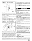
Rotating the Venter Assembly
1,
2,
3,
4,
5.
6.
If gas and electrical power have already been connected to
unit shut off gas and remove power from unit. Unscrew screws
on burner compartment door and remove burner compartment
door. (see Figure 6).
Disconnect power leads to the venter motor and hose to pres-
sure switch. Remove three (3) or four (4) screws which secure
the venter to the collector box, (see Figure 7).
Cut webbing with a pair of snips holding the vent plate to the
cabinet on either the left or right side of unit depending on right
or left venting as desired. Discard vent plate, (see Figure 6).
Replace venter gasket (part # 1013540, if needed) to venter
assembly with adhesive in the same location as the old one.
Clip the wire tie for the venter wires, if needed.
Rotate venter assembly 90 ° right or left from original location
depending on venting configurations.
kinking of the pressure switch hose, trim the hose to remove ex-
cess length.
Note: When drilling new holes make sure metal shavings do not fall
on or in components, as this can shorten the life of the furnace.
Typical Downflow Installation
RETURN
AIR
See side venting
Combustible floor
base outlet flange
adapter
Vent Shield
Kit MUST BE OPPOSITE
VENT DISCHARGE
SIDE
SUPPLY
AIR 25-23-19
Furnace with Screws
Venter Gasket
Main Line Entry
Screws (2)
25-23-45
25-23-52c 25-23-52b
441 01 2613 02