


iiiiiiiiiiiiiiiii_!!!!!!!!:!i:iil¸;i¸ii¸ii¸ii¸ii¸ii¸ii¸ii¸i¸ii¸ii¸ii¸iiiiliiiiii;;;iiiiiiii;i;il;i;i;i;iiii_ilili;i;i;i;;i;i;il;i;iiiii¸i;iiiii!!!
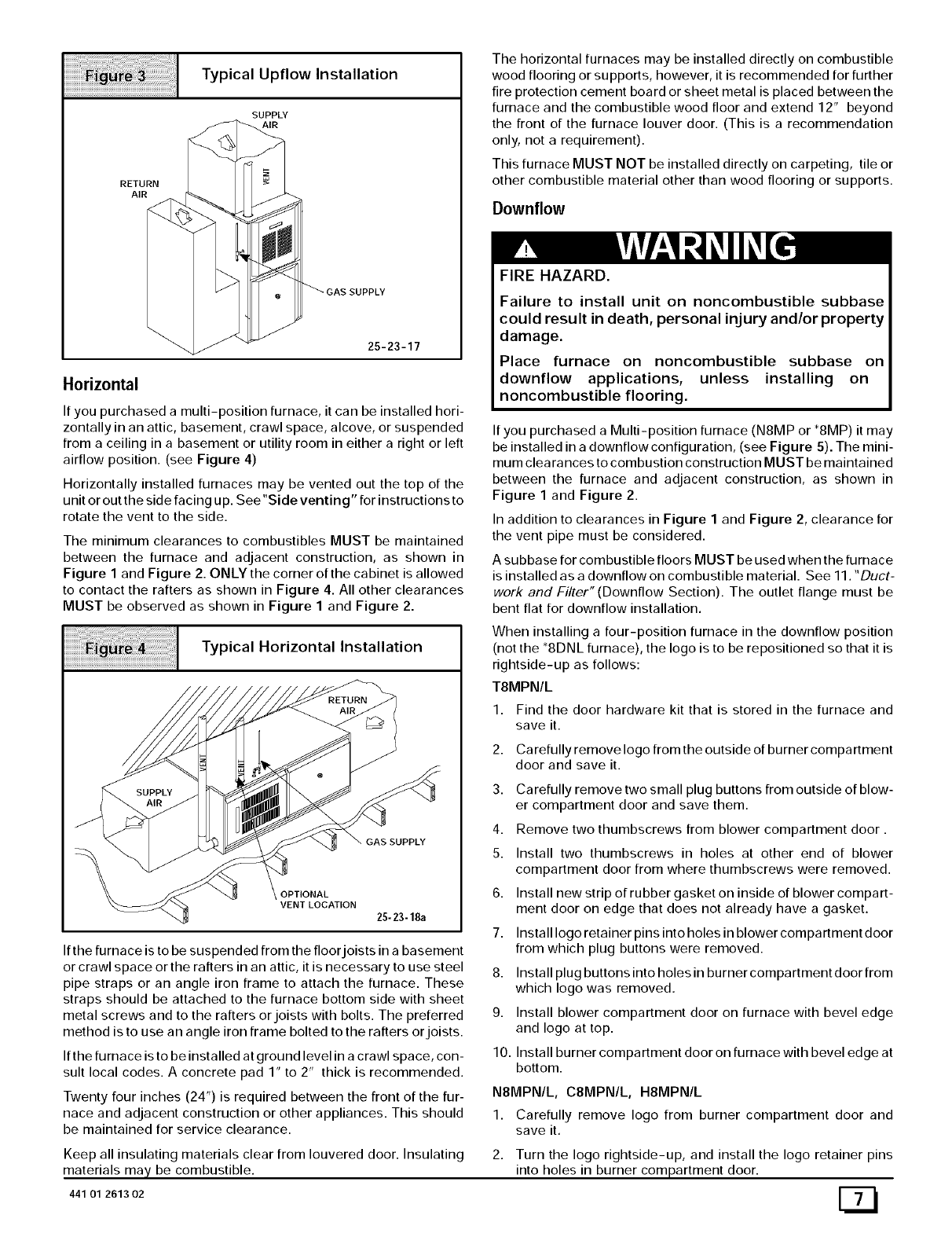
i!i!i!i!i!i!i!i!i!i!i! i i i i i ii i ! i ! i!! i!i!!i!iiii! iiiiiiiiiiiiiiiiiiiiiiiiiiiiiiiiiiiiiii i i i i i T p,ca,Up.ow,nsta.at,on
SUPPLY
AIR
RETURN N
GAS SUPPLY
25-23-17
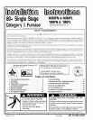
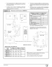
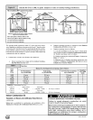
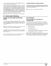
Horizontal
If you purchased a multi-position furnace, it can be installed hori-
zontally in an attic, basement, crawl space, alcove, or suspended
from a ceiling in a basement or utility room in either a right or left
airflow position. (see Figure 4)
Horizontally installed furnaces may be vented out the top of the
unit or out the side facing up. See"Side venting" for instructions to
rotate the vent to the side.
The minimum clearances to combustibles MUST be maintained
between the furnace and adjacent construction, as shown in
Figure 1 and Figure 2. ONLY the corner of the cabinet is allowed
to contact the rafters as shown in Figure 4. All other clearances
MUST be observed as shown in Figure 1 and Figure 2.
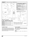
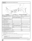
Typical Horizontal Installation
GAS SUPPLY
SUPPLY
OPTIONAL
VENT LOCATION
25- 23-18a
The horizontal furnaces may be installed directly on combustible
wood flooring or supports, however, it is recommended for further
fire protection cement board or sheet metal is placed between the
furnace and the combustible wood floor and extend 12" beyond
the front of the furnace louver door. (This is a recommendation
only, not a requirement).
This furnace MUST NOT be installed directly on carpeting, tile or
other combustible material other than wood flooring or supports.
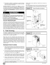
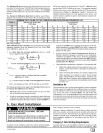
Downflow
FIRE HAZARD.
Failure to install unit on noncombustible subbase
could result in death, personal injury and/or property
damage.
Place furnace on noncombustible subbase on
downflow applications, unless installing on
noncombustible flooring.
If you purchased a Multi-position furnace (N8MP or *8MP) it may
be installed in a downflow configuration, (see Figure 5). The mini-
mum clearances to combustion construction MUST be maintained
between the furnace and adjacent construction, as shown in
Figure 1 and Figure 2.
In addition to clearances in Figure 1 and Figure 2, clearance for
the vent pipe must be considered.
A subbase for combustible floors MUST be used when the furnace
is installed as a downflow on combustible material. See 11. "Duct-
work and Filter" (Downflow Section). The outlet flange must be
bent flat for downflow installation.
When installing a four-position furnace in the downflow position
(not the *8DNL furnace), the logo is to be repositioned so that it is
rightside-up as follows:
T8MPN/L
1. Find the door hardware kit that is stored in the furnace and
save it.
2. Carefully remove logo from the outside of burner compartment
door and save it.
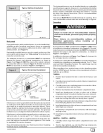
If the furnace is to be suspended from the floor joists in a basement
or crawl space or the rafters in an attic, it is necessary to use steel
pipe straps or an angle iron frame to attach the furnace. These
straps should be attached to the furnace bottom side with sheet
metal screws and to the rafters orjoists with bolts. The preferred
method is to use an angle iron frame bolted to the rafters or joists.
If the furnace is to be installed at ground level in a crawl space, con-
sult local codes. A concrete pad 1" to 2" thick is recommended.
3. Carefully remove two small plug buttons from outside of blow-
er compartment door and save them.
4. Remove two thumbscrews from blower compartment door.
5. Install two thumbscrews in holes at other end of blower
compartment door from where thumbscrews were removed.
6. Install new strip of rubber gasket on inside of blower compart-
ment door on edge that does not already have a gasket.
7. Install logo retainer pins into holes in blower compartment door
from which plug buttons were removed.
8. Install plug buttons into holes in burner compartment door from
which logo was removed.
9. Install blower compartment door on furnace with bevel edge
and logo at top.
10. Install burner compartment door on furnace with bevel edge at
bottom.
Twenty four inches (24") is required between the front of the fur-
nace and adjacent construction or other appliances. This should
be maintained for service clearance.
N8MPN/L, C81VlPN/L, H8MPN/L
1, Carefully remove logo from burner compartment door and
save it.
Keep all insulating materials clear from Iouvered door. Insulating
materials may be combustible.
441 01 2613 02
2. Turn the logo rightside-up, and install the logo retainer pins
into holes in burner compartment door.