


9. Electrical Wiring
ELECTRICALSHOCK HAZARD.
Failure to follow safety warnings exactly could
result in death or personal injury.
Turn OFF electrical power at fuse box or service
panel before making any electrical connections
and ensure a proper ground connection is made
before connecting line voltage.
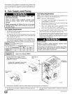
Power Supply Wiring
The furnace MUST be electrically wired and grounded in accor-
dance with local codes, or in the absence of local codes, with the
National Electrical Code (NEC), ANSI/NFPA 70-2002 in the U.S.,
or the Canadian Electrical Code (CEC), CSA C22.1 in Canada.
The power supply to the furnace connections must be between
104 VAC and 127 VAC during furnace operation for acceptable
performance.
Field wiring connections must be made inside the furnace connec-
tion box. A suitable strain relief should be used at the point the
wires exit the furnace casing.
Copper conductors shall be used. Line voltage wires should
conform to temperature limitation of 63 ° F (35 ° C) rise. Wire and
circuit breaker sizing shall be based on the ampacity of the furnace
electrical components plus the amps for all installed accessories
(1.0 amps total for EAC and HUM). Ampacity can be determined
by using the NEC or CEC.
NOTE: Furnace will not have normal operation if line polarity is re-
versed. Check ALL field and control connections prior to opera-
tion.
Furnace must be installed so the electrical components are pro-
tected from water and connected to its own separate circuit.
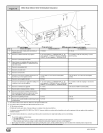
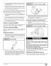
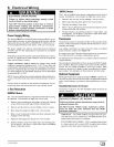
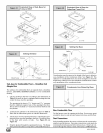
J- Box Relocation
N8MPN/L Models
The J-box is installed in blower compartment on left side of casing.
An alternate J-box location on right side can be used.
1. Remove bag containing two hole plugs and two self-tapping
screws from loose parts bag in blower compartment.
2. Remove and discard two screws holding J-box to casing.
3. Move large hole plug from right to left J-box location.
4. Move J-box to alternate location and attach using two self-
tapping screws from bag.
5. Apply two hole plugs from bag at left J-box location.
6. Position all wires away from sharp edges and moving parts.
Do not pinch J-box wires or other wires when reinstalling
blower compartment door.
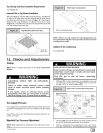
*8MPN/L Models
The J-box is installed in the burner compartment on left side of
casing. An alternate J-box location on right side can be used:
1. Remove and save two screws holding J-box to casing.
2. Move large hole plug from right to left J-box location.
3. Clip wire tie holding J-box wires.
4. Move J-box to alternate location and attach using two screws
removed from left side location.
Position all wires away from hot surfaces, sharp edges, and
moving parts. Do not pinch J-box wires or other wires when
reinstalling burner compartment door.
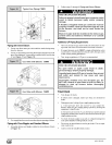
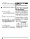
Thermostat
Thermostat location has an important effect on the operation of the
furnace. Follow instructions included with thermostat for correct
mounting and wiring.
Low voltage connections to furnace must be made on terminal
board to furnace control. (See Figure 19)
If cooling is used, the Y from the thermostat must be connected to
the control board Y to energize cooling blower speed.
Set thermostat heat anticipator in accordance with the Technical
Support Manual.
Heat anticipator setting will need to be measured if 24VAC humidi-
fier is installed. Measure currentin series from R to W at thether-
mostat. Be sure 24VAC humidifier is wired up to control. Allow
furnace to operate for 2 minutes before recording the AC amper-
age reading. Set anticipator on thermostat to recorded value.
Optional Equipment
All wiring from furnace to optional equipment MUST conform to lo-
cal codes or, in the absence of local codes, the applicable national
codes. Install wiring in accordance with manufacturer's instruc-
tions.
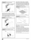
Humidifier/Electronic Air Cleaner
The furnace is wired for 115 VAC humidifier and/or electronic air
cleaner connection.
REDUCED FURNACE LIFEHAZARD
Failure to follow caution instructions may result in
reduced furnace life.
Do NOT exceed 115V/1.0 amp. maximum current
load for both the EAC terminal and the HUM
terminal combined.
HUMIDIFIER - The 24VAC HUM is energized when the pres-
sure switch closes on a call for heat. The HUM (115VAC) is en-
ergized when the inducer is energized.
ELECTRONIC AIR CLEANER - EAC is energized when there
is a blower speed call, except is NOT energized when blower
operates in the hard-wired continuous fan mode.
441 01 261302 [_