


Top
Humidifier
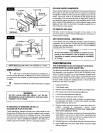
Plenum--->
_.5" Minimum Clearance
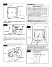
O
o
-Drill (3)
Holes
1/8" Dia.
- Cut
Opening
•Level Line
& Bottom of
Humidifier
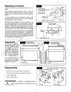
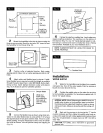
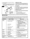
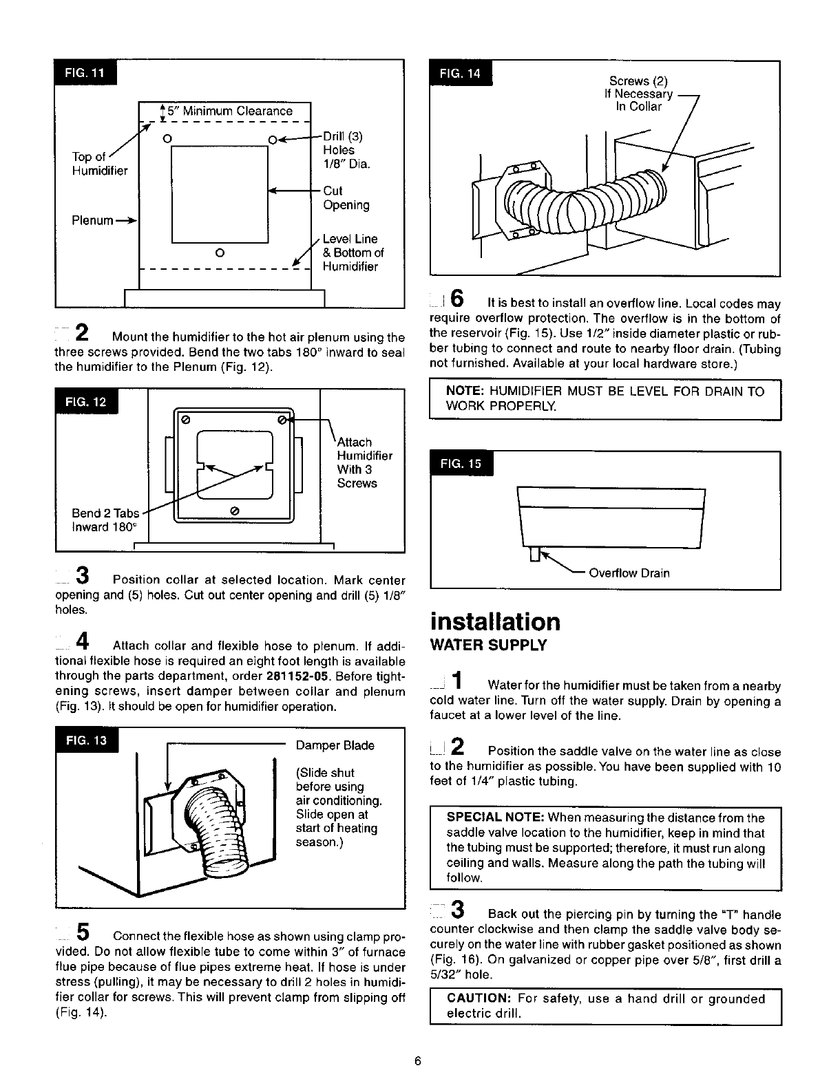
2 Mount the humidifier to the hot air plenum using the
three screws provided. Bend the two tabs 180° inward to seal
the humidifier to the Plenum (Fig. 12).
Bend 2 Tabs -
Inward 180°
Humidifier
With 3
Screws
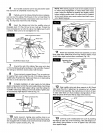
Position collar at selected location. Mark center
opening and (5) holes. Cut out center opening and drill (5) 1/8"
holes.
4 Attach collar and flexible hose to plenum. If addi-
tional flexible hose is required an eight foot length is available
through the parts department, order 281152-05. Before tight-
ening screws, insert damper between collar and plenum
(Fig. 13). it should be open for humidifier operation.
Damper Blade
(Slide shut
before using
air conditioning.
Slide open at
start of heating
season.)
;_1 Connect the flexible hose as shown using clamp pro-
vided. Do not allow flexible tube to come within 3" of furnace
flue pipe because of flue pipes extreme heat. If hose is under
stress (pulling), it may be necessary to drill 2 holes in humidi-
fier collar for screws. This will prevent clamp from slipping off
(Fig. 14).
Screws (2)
If Necessary "_t
ar/
i 6 It is best to install an overflow line. Local codes may
require overflow protection. The overflow is in the bottom of
the reservoir (Fig. 15). Use 1/2" inside diameter plastic or rub-
ber tubing to connect and route to nearby floor drain. (Tubing
not furnished. Available at your local hardware store.)
NOTE: HUMIDIFIER MUST BE LEVEL FOR DRAIN TO I
WORK PROPERLY.
I
_ Overflow Drain
installation
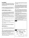
WATER SUPPLY
J1 Water for the humidifier must be taken from a nearby
cold water line. Turn off the water supply. Drain by opening a
faucet at a lower level of the line.
i J2 Position the saddle valve on the water line as close
to the humidifier as possible. You have been supplied with 10
feet of 1/4" plastic tubing.
SPECIAL NOTE: When measuring the distance from the
saddle valve location to the humidifier, keep in mind that
the tubing must be supported; therefore, it must run along
ceiling and walls. Measure along the path the tubing will
follow.
3 Back out the piercing pin by turning the "T" handle
counter clockwise and then clamp the saddle valve body se-
curely on the water line with rubber gasket positioned as shown
(Fig. 16). On galvanized or copper pipe over 5/8", first drill a
5/32" hole.
CAUTION: For safety, use a hand drill or grounded
electric drill.
6