


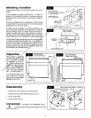
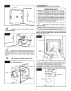
Turnhandleclockwiseuntilithaspiercedthewater
lineandvalveiscompletelyclosed(Fig.16).
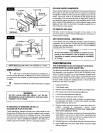
, _ Partiallyuncoilthetubing.Slidethebrasscompres-
sionnutoverthetubing.Thethreadsinthenutmustfacethe
tubingend.Placethebrasscompressionsleeveasshownin
Fig. 16. Slip brass insert into end of tubing.
1,1[_ U:!
_ U Insert the tubing end into the saddle valve at
threaded stem "A" (Fig. 16) as far as it will go. Thread the
brass compression nut onto the valve, then tighten gently with
a wrench. Take care not to overtighten the nut.
l;Ke'_il[,_B
Brass Compression Sleeve
f Brass Insert
Brass
Compression Nut
MOUNTING SADDLE VALVE
Water Pipe
.A,,
Rubber Gasket
(Stem Up)
7 Unwind the rest of the tubing. Take care not to kink
it. Run the tubing along flat surfaces to the humidifier. Support
the tubing as needed to avoid contact with furnace.
0
__ O Close previously opened faucet. Turn on main wa-
ter supply. Place a pail under the end of the tubing. Open the
saddle valve. Flush the line. Make sure there are no leaks along
the line or at the valve. Turn valve off.
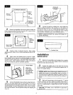
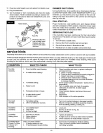
Complete installation of water supply by first sliding
plastic compression nut onto the water supply tubing. Insert brass
insert into the end of water supply tubing. Insert the tubing into
humidifier valve body, making sure it is fully seated. Tighten plas-
tic nut securely, finger tight (no wrench) (Fig. 17).
l=[_=_ilrd
Plastic Compression Nut
t--p,ost,o
3rass Insert Water Line
WARNING:
BrassInsert MustBe Installed
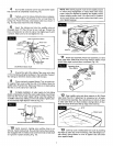
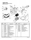
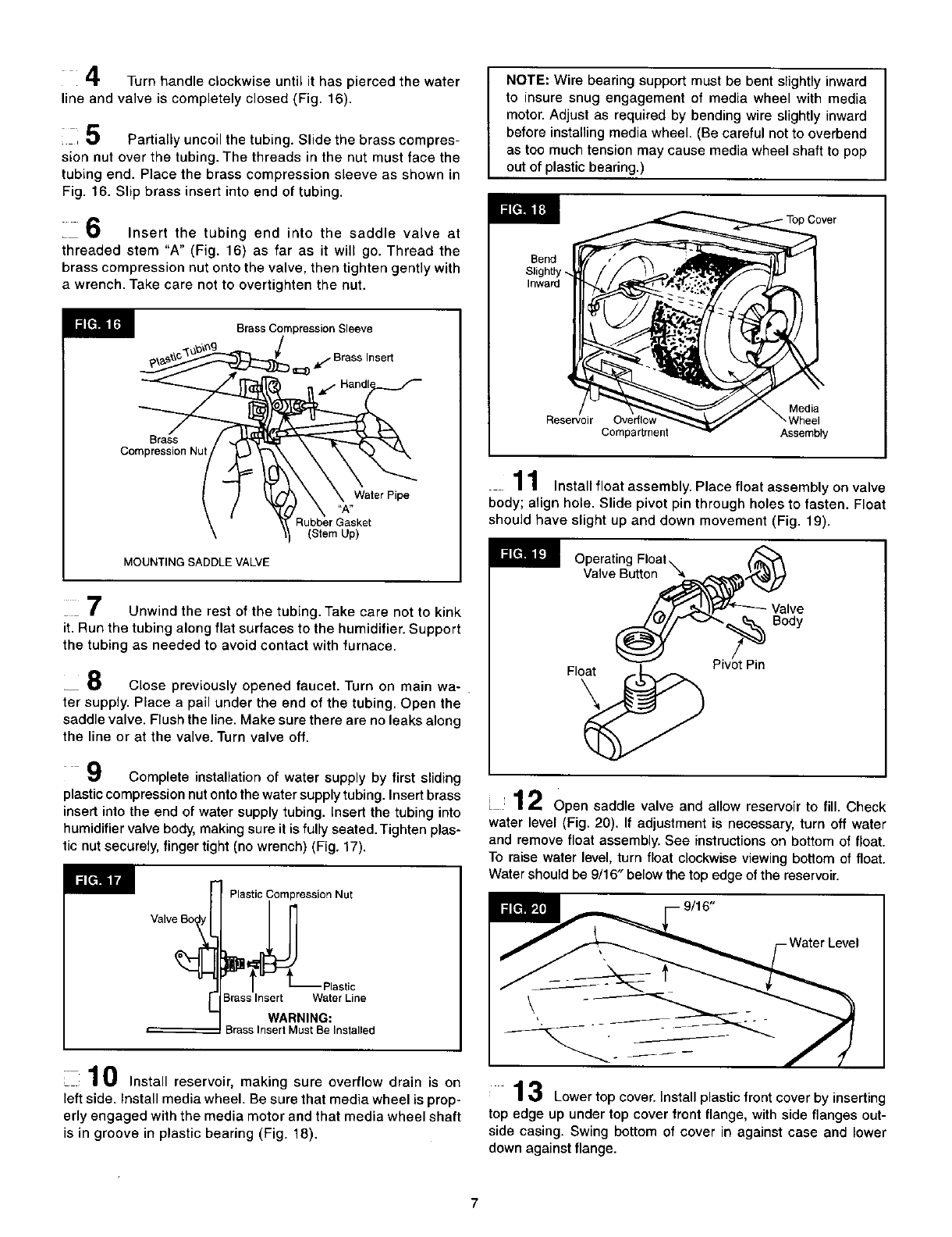
10 Install reservoir, making sure overflow drain is on
left side. Install media wheel. Be sure that media wheel is prop-
erly engaged with the media motor and that media wheel shaft
is in groove in plastic bearing (Fig. 18).
NOTE: Wire bearing support must be bent slightly inward
to insure snug engagement of media wheel with media
motor. Adjust as required by bending wire slightly inward
before installing media wheel. (Be careful not to overbend
as too much tension may cause media wheel shaft to pop
out of plastic bearing.)
Cover
Bend
Slightly _.
Inward
Reservoir Overflow
Compartment
Media
Wheel
Assembly
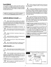
11 Install float assembly. Place float assembly on valve
body; align hole. Slide pivot pin through holes to fasten. Float
should have slight up and down movement (Fig. 19).
Operating Float \
Valve Button
Body
Pivot Pin
[ 12 Open saddle valve and allow reservoir to fill. Check
water level (Fig. 20). If adjustment is necessary, turn off water
and remove float assembly. See instructions on bottom of float.
To raise water level, turn float clockwise viewing bottom of float.
Water should be 9/16" below the top edge of the reservoir.
3 Lower top cover. Install plastic front cover by inserting
top edge up under top cover front flange, with side flanges out-
side casing. Swing bottom of cover in against case and lower
down against flange.
7