


Water Piping
WARNING
HOTTER WATER CAN SCALD: Water heaters are intended to
produce hot water. Water heated to a temperature which
will satisfy clothes washing, dishwashing, and other sanitiz-
ing needs can scald and permanently injure you upon con-
tact. Some people are more likely to be permanently injured
bY hot water than others. These include tile elderly, children,
the infirm, or physically/mentally handicapped. If anyone
using hot water in your home fits ,nto one of thesegroups or
if there is a local code or state law requiring a certain tem-
perature water at the hot water tap, then you must take spe-
cial precautions, in addition to usingthe lowest possibletem-
perature setting that satisfies your hot water needs, some
type of tempeffng device, such asa mixing valve, should be
used at the hot water tapsused by these people or at the
water heater. Mixing valves are available at plumbing supply
or hardware stores. Follow manufacturers instructions for
installation of the valves. Before changing the factory setting
on the thermostat, read the "Temperature Regulation" section
in this manual.
This water heater shall not be connected to any heating
systems or component(s) used with a non-potable water
heating appliance.
NOTE: To protect against untimely corrosion of hot and
cold water fittings, ]t is strongly recommended that di-
electric unions or couplings be installed on this water
heater when connected to copper pipe.
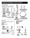
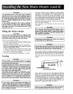
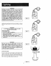
The illustration Shows the attachment of the water piping
to the water heater. The water heater is equipped with ¾
inch water connections.
NOTE: If using copper tubing, solder tubing to an
adapter before attaching the adaptor to the cord water
inlet connection. Do not solder the cold water supply
llne directly to the cold water inlet. It will harm the dip
tube and damage -the tank.
1. Look at the top cover of the water heater. The water
outlet is marked hot. Put two or three turns of teflon
tape around the threaded end of the threaded-to-sweat
coupling and around both ends of the ¼"threaded nip-
ple. Using flexible connectors, connect the hot water
pipe to the hot water outlet on the water heater.
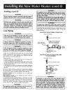
INSTALLATION COMPLETED USING
SEARS INSTALLATION KIT
SHUTOFF
HOT OUTLET FLEXIBLEWATER VALVE
TO HOUSE CONNECTORS
-_-'--'ac_gl)_JJ,_j<._- _.1. +._ $ :_ _ COLDwATERINLETLINE
THREADEDtO _. ! $ I _ THREADEDTO
SwEatcOUPLznG = / . sweat cOuPLlnC
-_ temPe_ture-
3/4" THREADED _ PRESSURE RELIEF
t0
.
Look at the top cover of the water heater. The cold
water inlet is marked cold. Put two or three turns
teflon tape around the threaded end of the threade6
to-sweat coupling and around both ends of the ¾"
threaded nipple, Using flexible connectors, connect
the cold water pipe to the cold water inlet of the water
heater.
NOTE: This water heater is super insulated to mini-
mize heat loss from the tank. Further reduction in
heat loss can be accomplished by insulating the hot
water lines from the water heater.
Temperature-Pressure Relief Valve
WARNING
At the time of manufacture this water heater was equipped
with a temperature-pressure relief valve. For protection
against excessive pressures and temperatures in this water
heater, install temperature-pressure protective equipment
required by local codes, but not less than a combination
temperature-pressure relief valve certified by nationally
recognized testing laboratory that maintains periodic
inspection of production of listed equipment or materials, as
meeting the requirements for Relief Valves and Automatic
Gas Shutoff Devices for Hot Water Supply Systems, the
latest edition ANSI Z21.22. This valve must be marked with
a maximum set pressure not to exceed the marked
hydrostatic working pressure of the water heater (150
Ibs./sq. in.). The reh'ef valve must be marked with
discharge capacity not lessthan the water heater Btu inpu.
rate as shown on the model rating plate.
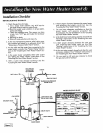
Install the temperature-pressure relief valve directly into the
fitting of the water heater. Position the valve downward and
prov,_e tubing so that any discharge will exit only within 6
inches above, or at any distance below the structural floor.
Be certain that no contact is made with any live electrical
part. The discharge opening must not be blocked or reduced
,'n size under any circumstances. Excessivelength, over 15
feet, or use of more than two elbows can cause restriction
and reduce the discharge capacity of the valve.
No valve or other obstruction is to be placed between the
relief valve and the tank. Do not connect tubing directly to
discharge drain unless a 6" air gap is provided. To prevent
bodily injury, hazard to life, or damage property, the relief
valve must be allowed to discharge water in quantities
should circumstances demand. If the discharge pipe is not
connected to a drain or other suitable means, the water
flow may.cause property damage.
The Discharge Pipe:
-Must not be smaller in size than the outlet pipe Size of the
valve, or have any reducing couplingsor other restriction.
-Must not be plugged or blocked.
-Must be of mater,'ai listed for hot water distribution.
-Must be installed so asto allow complete drainage of both
the temperature-pressure relief valve, and the discharge
pipe.
-Must terminate at an adequate drain.
-Must not have any valve between the relief valveand tank.
If the water heater is installed using a check valve in tff
water line or a water meter with a check valve, contac
the local uti]ity or local Sears Service Center on how to
control this situation.