


Installation Instructions (cont'd)
Gas Piping
I AWARNING ]
Make sure the gassure type listedon the I
modelrating plate. The inlet gaspressuremust not exceed
14incheswater column 'Apoundper squareinch(3.5kPa)].I
The minimum inlet gaspressurelistedon the model rating I
plateisforthe purposeofinputadjustment.
AWARNING , J
Ifthe gascontrolvalveissubjectedto pressuresexceeding'A
poundper square inch(3.5kPa),the damageto the gascon-
trolvalvecouldresult ina fireor expiosionfrom leakingga_ J
AWARNING
If the main gasline shutoffservingall gasappliancesisused,
alsotorn "off" the gasat eachappliance.Leaveall gasappli-
ancesshutoffuntildmwater heaterinstallationiscomplete.
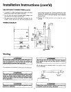
A gas line of sufficient size must be run to the water heater.
Consult the latest edition of National Fuel Gas Code ANSI
Z223.1, also referred to as NFPA54 and the gas company con-
cerning pipe size.
There must be:
•A readily accessiblemanual shut off valve in the gas supply line
serving the water heater, and
•A drip leg (sediment trap) aheadof the gas control valve to help
prevent dirt and foreign materials from entering the gas control
ValVe.
•A flexible gas connector or a ground joint union between the
shutoffvalve and control valveto permit servicing of the unit.
Be sure to check all the gas piping for leaks before li_hting the
water heater. Use a soapy water solution, not a match or open
flame. Rinse offsoapy solution and wipe dry.
Standard Models are for installation up to 3,300 feet above sea
level.
High Altitude Models are for installation from 3,300 to 5,500
feet above sea level.
Ifa standard model is installed above 3,300 feet or a high altitude
model is installed above 5,500 feet, the input rating must be
reduced at the rate of 4 percent for each 1,000 feet above sea level.
Contact your local Sears Service Center or gas utility for further
information.
AWARNING be leak tested
The appliance and its gasconnectionmust
beforeplacingthe appliancein operation.
f AWARNING J
Use pipe joint €omp_tape marked as beingI
resistantto the actionofpetroleum[Propane(LR)] gese_ 1
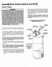
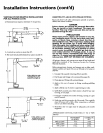
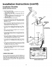
SEDIMENT TRAP
A sediment trap shall be installed as close to the inlet of the
water heater as practical at the time of water heater installation.
The sediment trap shall be either a tee fitting with a capped nip-
ple in the bottom outlet or other device recognized as an effec-
tive sediment trap. If a tee fitting is used, it shall be installed in
conformance with one of the methods of installation shown
below.
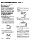
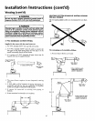
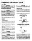
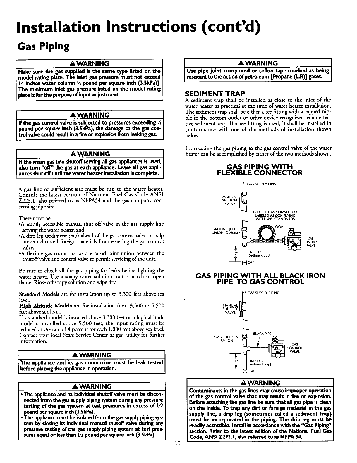
Connecting the gas piping to the gas control valve of the water
heater can be accomplished by either of the two methods shown.
GAS PIPING WITH
FLEXIBLE CONNECTOR
MANUAL _('AS SUPPLY PIPING
SHUTOFF
VALVE
FLEXIBLEG_S CONNECTOR
LABELED AS COMPLYING
WITH ANSI STANDARDS
GROUND
UNION (Optional)
DRIP LEG
(Sediment trap)
CAP
GAS
CONTROL
VALVE
GAS PIPING WITH ALL BLACK IRON
PIPE TO GAS CONTROL
MANUAL_;ASSUPPLY PIING
SHUTOFF
VALVE
GROUND lOIN1
UNION
T
6"
BLACK PIPE
DRIP LEG
(Sediment t_ap)
CAP
GAS
CONTROL
VALVE
AWARNING
• The applianceand itsindividualshutoffvalvemust bediscon-
nectedfromthe gassupplypipingsystemduringanypressure
testingofthe gassystemat test pressuresin excessof I/2
poundpersquareinch(3.5kPa).
• The appliancemust beisolatedfromthegassupplypipingsys-
tem byclosingits individualmanualshutoffvalveduringany
pressuretestingofthe gassupplypipingsystemat test pres-
suresequalorlessthan I/2poundpersquareinch(3.5kPa).
19
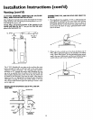
&WARNING
Contaminants in the gaslinesmaycauseimproperoperation
of the gascontrolvalvethat may resultinfire or explosion.
Beforeattachingthe gasline be surethat all gaspipe isclean
on the inside.To trap anydirt or foreign material in the gas
supplyline, a drip leg (sometimes calleda sediment trap)
must be incorporated in the piping.The drip leg must be
readily accessible.Installin accordancewiththe "Gas Piping"
section.Referto the latestedition of the National FuelGas
Code,ANSI Z223.1,alsoreferred to asNFPA54.