


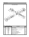
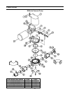
3
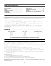
Electrical Wiring
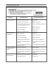
It is imperative that adequate wire size and proper over-current protection (fuse or circuit breaker) sizes are used.
The following chart can be used as a guideline. Refer to chart on page 10 for solenoid/relay information.
12 VDC
24 VDC
32 VDC
115 VAC (1 phase)
230 VAC (1 phase)
6 to 8 ga.
8 to 10 ga.
10 to 12 ga.
12 to 14 ga.
14 to 16 ga.
3 to 4 ga.
6 to 8 ga.
8 to 10 ga.
10 to 12 ga.
12 to 14 ga.
50 amp
25 amp
20 amp
10 amp
5 amp
75 amp
40 amp
30 amp
15 amp
8 amp
PUMP VOLTAGE
PUMP MOTOR WIRE SIZE
BREAKER/FUSE SIZE
1/2 HP
3/4 HP
1/2 HP
3/4 HP
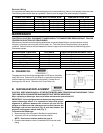
Maintenance Procedure
Procedure
Approximate Maintenance Level
MAINTENANCE
ELECTRICAL CAUTION: DISCONNECT POWER SUPPLY TO PUMP BEFORE SERVICING UNIT. FOLLOW
PROPER LOCK-OUT/TAG-OUT PROCEDURES.
Maintenance intervals and normal parts replacement vary widely depending on numerous factors such as
frequency of system use and quality of flush water, etc. The chart below is intended strictly as a general
guideline. Owner discretion and consideration of actual usage must be the first basis for determining proper
maintenance levels.
Change Oil
Inspect Diaphragm
Inspect Rod Bushing
Inspect Eccentric Pin
Duckbill Valve Replacement
Speed Reducer Replacement
Motor Replacement
A
B
C
D
E
F
G
See instructions
Every two years
Every two years
Every two years
Every two years
If needed
If needed
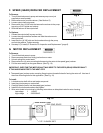
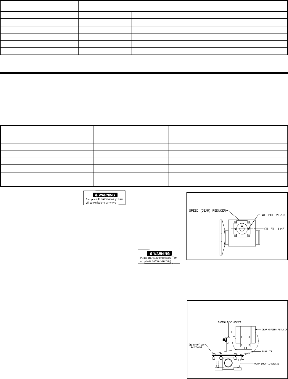
A. CHANGE OIL
The gear reducer oil should be changed after first 50 hours, thereafter
every 200 hours. Drain and fill with 90W oil or equivalent to bottom of
oil level inspection hole (opposite of output shaft). Grease the rod
bushing every 200 hours. (See item 9 on Pump Parts List)
B. DIAPHRAGM REPLACEMENT
CAUTION: KEEP HANDS AND ALL OTHER EXTREMITIES AWAY FROM ROD AND DIAPHRAGM. FLUSH
THE PUMP WITH CLEAN WATER AND DISINFECTANT BEFORE SERVICING.
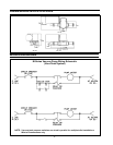
When replacing a diaphragm, be sure to follow maintenance instructions B-D.
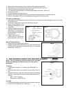
IMPORTANT: Incorrect alignments and clearances may cause pre-
mature diaphragm failure. It is important to insure that proper
alignment is achieved between the eccentric pin and the dia-
phragm rod. Make sure that clearances are correct between the
diaphragm rod and the eccentric (Fig. 6) and also between the
eccentric and the gear reducer hub (Fig. 7).
To Remove the Diaphragm:
1. Remove pump cover (not used in SaniService applications).
2. Jog motor until rod is at bottom dead center position.
NOTE: See manual rotation method on page 4.
3. Close the maintenance valves (if installed) in the inlet and outlet
piping.
Fig. 2
Fig. 1