


19
English
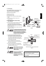
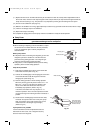
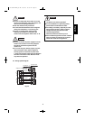
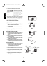
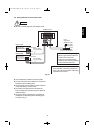
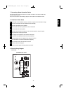
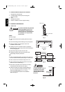
7. Connecting a Home Automation Device
The HA (white) 4P terminal is located on the indoor unit PCB. If a HA device will be used,
connect it to this terminal.
Also, refer to Section 9. Electric Wiring Diagram in the outdoor unit installation manual.
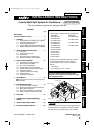
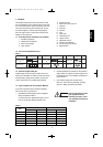
8. Installation Check Sheet
The strength of the installation location is sufficient to support the Air Conditioner weight.
The indoor and outdoor units are installed level and vertically.
The power and voltage are as specified.
Inter-unit cables are securely fastened to the terminal board.
Inter-unit cables are securely fixed.
The power cord and inter-unit cables are not connected anywhere along their paths.
The ground wire is securely connected.
An air purge of the refrigerant circuit has been conducted.
A leak test of the tubing connections has been performed.
Thermal insulation has been applied to the tubing connections.
Drain connections are secure and water drains properly.
Putty has been used to close the hole in the wall.
All service valves are fully open.
Remote controller signals are being positively received.
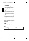
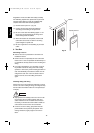
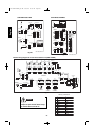
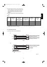
9. Electric Wiring Diagram
Indoor Unit
EVAPORATOR
TERMINAL BASE
WHT
BLK
RED
1
2
3
4
YEL/GRN
LAMP
10P(
WHT
)
FLAP
5P(WHT)
FLAP
CONNECTOR
FLAP MOTOR
RED
PNK
BLU
BRN
YEL
1
2
3
4
5
1
2
3
4
5
1
2
3
4
5
1
2
3
4
5
AC1 AC2 SI
WHT
RED
WHT
WHT
WHT
WHT
WHT
WHT
WHT
WHT
1
2
3
4
5
6
7
8
9
10
1
2
3
4
5
6
7
8
9
10
1
2
3
4
5
6
7
8
9
10
1
2
3
4
5
6
7
8
9
10
IND LAMP ASSY
ROOM/COIL
4P(
WHT
)
DCM
6P(BLU)
CONTROLLER
FM
FAN MOTOR
RED
1
2
3
4
5
6
1
2
3
4
5
6
WHT
BLK
YEL
BLU
ROOM THERMISTOR
BLK
BLK
BLK
BLK
1
2
3
4
1
2
3
4
COIL THERMISTOR
ION
3P(
WHT
)
HA
JEM-A
1
2
3
1
2
3
1
2
3
1
2
3
4P(
WHT
)
1 2 4
BLK
3
BLK
BLK
RED
WHT
1 2 3 4
1 2 3 4
ION ASSY
ION
TERMINAL
TO OUTDOOR UNIT
WHT
RED
BLK
CONNECTOR
SAP-KMRV74/94/124EH
8FA-2-5257-72600-1
Fig. 33a
08-245 CMRV1426EH_OU EN 9/22/08 10:35 AM Page 19