


18
S4359128
6. Electrical Wiring
6-1. General Precautions on Wiring
(1) Before wiring, confirm the rated voltage of the unit
as shown on its nameplate, then carry out the
wiring closely following the wiring diagram.
(2) Provide a power outlet to be used exclusively for
each unit, and a power supply disconnect and
circuit breaker for overcurrent protection should
be provided in the exclusive line.
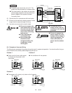
(3) To prevent possible hazards from insulation
failure, the unit must be grounded.
(4) Each wiring connection must be done in accor-
dance with the wiring system diagram. Wrong
wiring may cause the unit to misoperate or
become damaged.
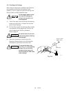
(5) Do not allow wiring to touch the refrigerant tubing,
compressor, or any moving parts of the fan.
(6) Unauthorized changes in the internal wiring can
be very dangerous. The manufacturer will accept
no responsibility for any damage or misoperation
that occurs as a result of such unauthorized
changes.
(7) Regulations on wire diameters differ from locality
to locality. For field wiring rules, please refer to
your LOCAL ELECTRICAL CODES (ex. National
Electric Code: ANSI/NFPA70) before beginning.
You must ensure that installation complies with all
relevant rules and regulations.
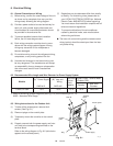
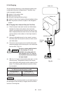
(8) To prevent malfunction of the air conditioner
caused by electrical noise, care must be taken
when wiring as follows:
● The inter-unit control wiring and the remote control
wiring (option) should be wired apart from the inter-
unit power wiring.
AWG #12 AWG #12
C1852, CL1852 75 ft. 65 ft. 15 A 20 A AWG #12
Models
6-2. Recommended Wire Length and Wire Diameter for Power Supply System
Time Delay
Fuse or
Circuit
Capacity
(B)
*1
Inter-unit
Wiring
(A)
*1
Power Supply
*1 Refer to the Wiring System Diagrams (See Fig. 6-3) for the meaning of “A”, “B”.
AWG = American Wire Gauge
Max. Wire
Diameter
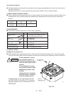
Power Supply Terminal Base
(Outdoor Unit)
Capacity
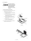
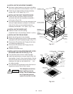
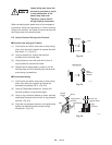
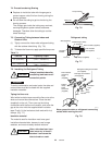
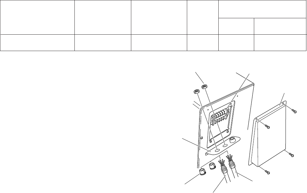
6-3. Wiring Instructions for the Outdoor Unit
(1) To take off the access panel, remove the 4
screws. (See Fig. 6-1)
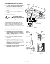
(2) Dismount plugs on the conduit plate.
(3) Temporarily mount the conduits on the conduit
plate.
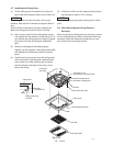
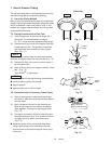
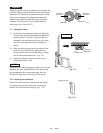
(4) Properly connect both the power supply and inter-
unit lines to the corresponding terminals on the
terminal block.
Refer to the wiring diagram in Fig. 6-2 (which also
appears on the access panel).
Lock nut
Terminal
block
Access panel
Power supply
Inter-unit line
Plug
Conduit
plate
1822_M_I
Fig. 6-1