


16
S4359128
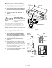
■ Wired Remote Control Unit (Option)
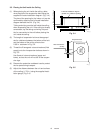
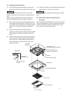
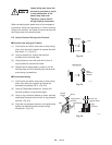
(1) To access the printed circuit board, remove the
cover plate of the electrical component box.
(2) Attach the remote control connectors securely to
the mating connector pins on the printed circuit
board.
(3) Turn the R.C.U. switch from “WIRELESS” to
“WIRED”.
(4) Replace the cover plate.
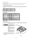
Do not supply power to
the unit until the tubing and
wiring to the outdoor unit is
completed.
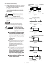
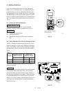
The mounting position for the remote control unit
should be located in an accessible place for control
and permit the average room temperature to be
detected. Never cover the unit or recess it into the wall.
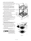
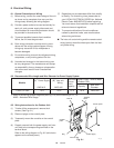
4-2. Installing the Wired Remote Control Unit
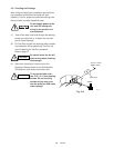
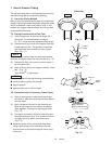
(1) Use a ballpoint pen or similar pointed object to
remove the plastic bushing which is inserted in
the rear of the remote control unit. The bushing
can be discarded. (Fig. 4-4)
(2) Align the cord with the groove of the remote
control unit.
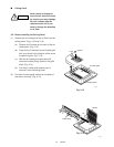
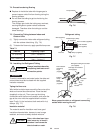
(3) Attach the mounting plate to the wall with the 2
supplied screws. Then align the rail on the rear of
the control unit with the slot of the mounting plate
and slide the unit down as far as it will go. (Fig. 4-4)
Fix the control unit cord to the wall.
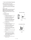
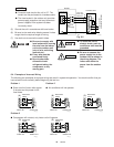
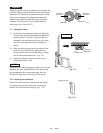
(4) If local codes allow, the remote control unit cord
can be wired in the wall. (Fig. 4-5)
Fig. 4-3
Fig. 4-5
Fig. 4-4
Cord
Rear
Groove
Plastic
bushing
Ballpoint
pen
Remote
control
unit
Wall
0531_M_I
Electrical
component box
Cover plate
Connector for the wired
remote control unit
1006_M_I
WIRED WIRELESS
R.C.U. Switch
Flat-head
tapping screw
25/64"(3 × 10 mm)
(SATA)
Cord clip
Remote
control
unit
Mounting
plate
Truss-head
tapping screw
5/8"(4 × 16 mm)
(TOTA)
1020_M_I