


16
3-7. Wire Size and Length
Regulations on wiring diameter differ from locality to locality. For field wiring requirements, please refer to your local elec-
trical codes. Carefully observe these regulations when carrying out the installation.
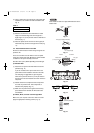
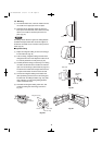
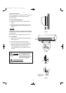
Refer to the wiring system diagram (Fig. 23) for the meaning of (A), (B), and (C) in Table 5.
Refer to your local codes or in the absence of local codes see the National Electric Code: ANSI/NFPA70.
NOTE
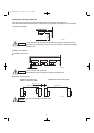
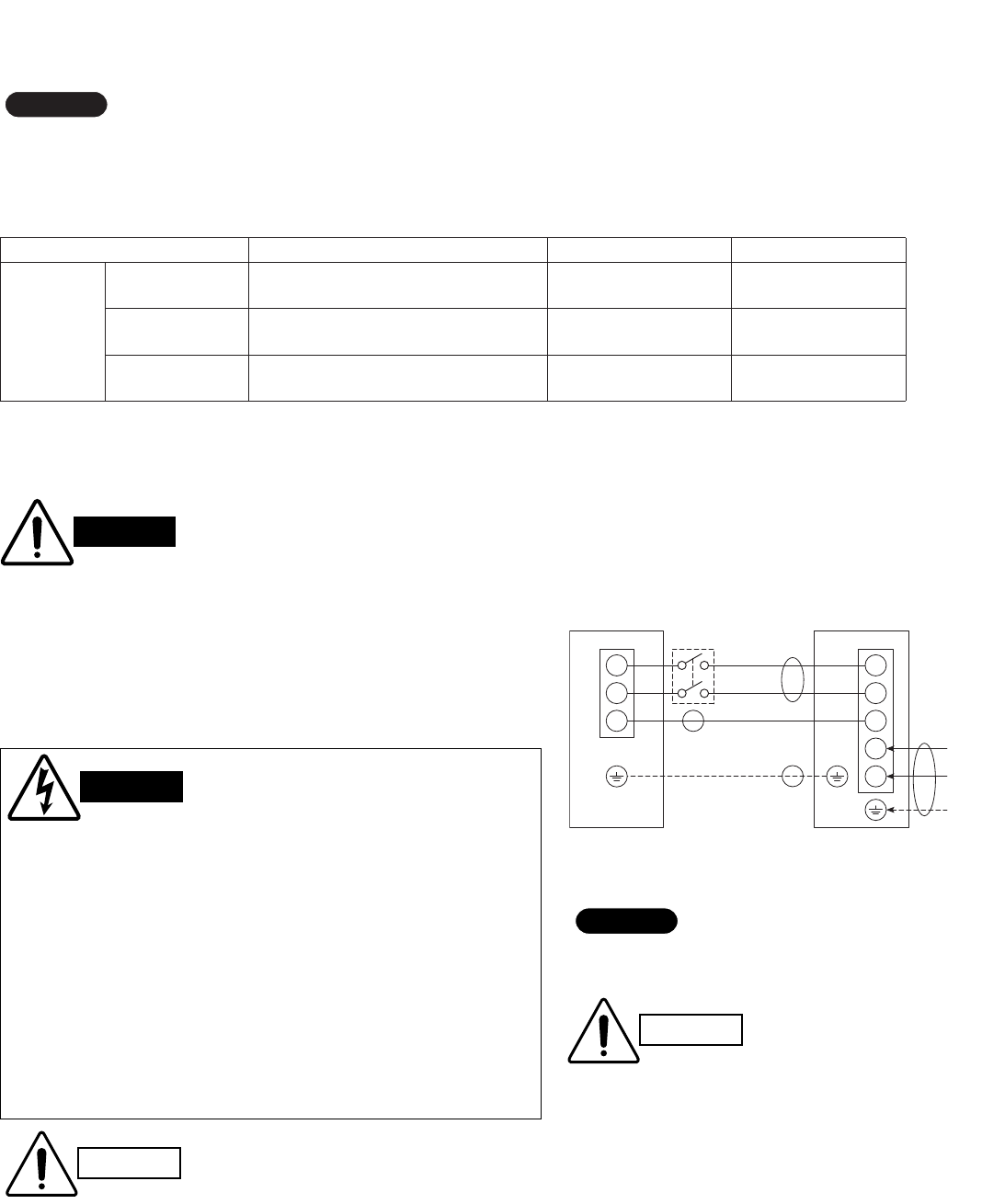
Fig. 23
WIRING SYSTEM DIAGRAM
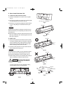
● Be sure to comply with local codes on running the wire
from the indoor unit to the outdoor unit (size of wire and
wiring method, etc.).
● Each wire must be firmly connected.
● No wire should be allowed to touch refrigerant tubing, the
compressor, or any moving part.
Disconnect
switch
*
1
2
3
1
2
3
4
5
Grounding line
INDOOR
UNIT
OUTDOOR
UNIT
Field supply
Grounding
line
L
1
L
2
Power supply
Single phase 230/208V 60Hz
Terminal Terminal
(A)
(B)
(C)
(B)
CAUTION
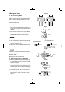
● Be sure to connect the power supply line to the outdoor unit as shown in the wiring diagram.
The indoor unit draws its power from the outdoor unit.
● Do not run wiring for antenna, signal, or power lines of television, radio, stereo, telephone,
security system, or intercom any closer than 3'4" (1 m) from the power cable and wires
between the indoor and outdoor units. Electrical noise may affect the operation.
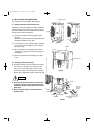
● To avoid the risk of electric shock, each air conditioner
unit must be grounded.
● For the installation of a grounding device, please
observe local electrical codes.
● Grounding is necessary, especially for units using
inverter circuits, in order to release charged electricity
and electrical noise caused by high tension.
Otherwise, electrical shock may occur.
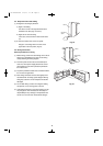
● Place a dedicated ground more than 7' (2 m) away from
other grounds and do not have it shared with other elec-
tric appliances.
WARNING
Table 5
WARNING
*
Disconnect switch may be required by
national or local codes.
Always comply with national and local code
requirements.
CAUTION
NOTE
Wire Size
Fuse or Circuit
Breaker Capacity
Length
CH3082
CH3682
It depends on wire specification and
supply voltage level (*2)
35A for CH3082
45A for CH3682
AWG12 (min.) or bigger (*1) for CH3082
AWG10 (min.) or bigger (*1) for CH3682
AWG14 or bigger
180 ft. (max.)
Disconnect switch
(15A)
AWG14 or bigger
180 ft. (max.)
(AWG: American Wire Gauge)
Model
(A) POWER SUPPLY WIRING (B) POWER LINE (C) CONTROL LINE
-
(*1) It depends on supply voltage level and wire specification. Consider temperature rating
of wire, ambient temperature, and the number of wires inside the conduit.
(*2) Requirement of supply voltage level: AC187V to 253V (Measure voltage level at terminal plate inside the outdoor unit.)
09-191 CH3082-3682 2/16/10 1:17 PM Page 16