


22
4. How to Install the Outdoor Unit
First refer to Section 2. Installation Site Selection.
4-1. Wiring Instructions for the Outdoor Unit
Regulations on wire size differ from locality to locality. For
field wiring requirements, please refer to your local elec-
trical codes. Make sure that the installation fully complies
with all local and national regulations.
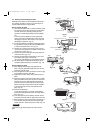
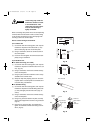
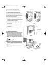
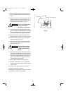
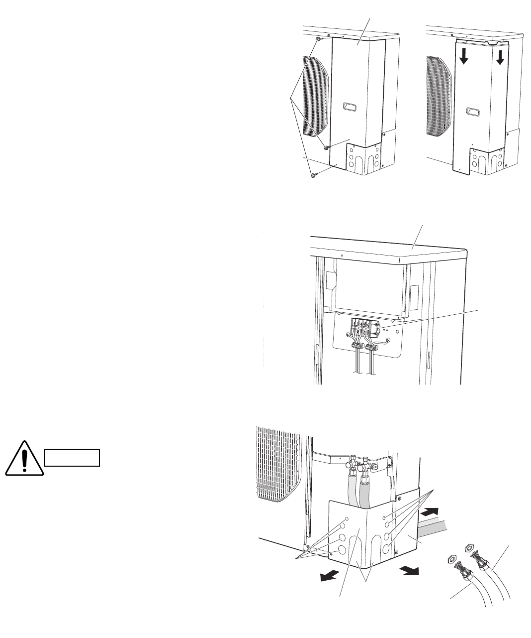
(1) Remove the 3 screws from the inspection panel.
(Fig. 46a)
Remove the inspection panel by sliding it downward
and pulling it toward you. (Fig. 46b)
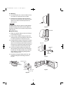
(2) Connect the inter-unit and power supply line accord-
ing to the wiring system diagram on the inspection
panel. (Fig. 46c)
(3) When connections are completed, check that all
connections are correct as shown in the wiring sys-
tem diagram.
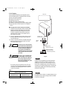
(4) Be sure to ground the unit according to your local
codes.
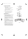
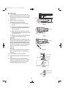
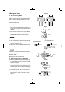
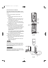
4-2. Routing the Tubing and Wiring
● The tubing and wiring can be extended out in 3 direc-
tions: front, rear, and right. Use a nipper or similar
tool to cut out the knockout holes for the inter-unit
control wiring outlet, power wiring outlet, and tubing
outlet from the appropriate covers A and B. (Fig. 46d)
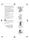
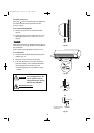
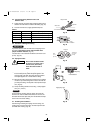
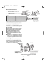
● Route the tubing so that it does not contact the
compressor, panel, or other parts inside the unit.
Increased noise will result if the tubing contacts
these parts.
● When routing the tubing, use a tube bender to
bend the tubes.
CAUTION
Terminal plate
Cabinet
Screw
Inspection panel
Fig.46a
Fig.46b
Fig.46c
Tubing outlet
Front
Right
Rear
Cover B
Cover A
Inter-unit
power line
Power supply line
(conduit)
Wiring outlet
Wiring outlet
(conduit)
Fig.46d
09-191 CH3082-3682 2/16/10 1:17 PM Page 22