


I-99
SM831148
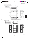
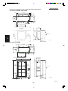
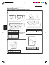
1. Specifications
1
2
3
4
5
6
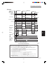
Indoor Unit
Control Wiring
Type
(B) Power Supply
AWG #14
(C) Inter-Unit Control Wiring (D) Remote Control Wiring
(E) Control Wiring For Group Control
Trade Size
of Conduit
MOP
(Fuse or HACR
type circuit breaker)
AWG #18
Use high voltage wire (300 V)
*1
AWG #18
*2
(0.75 mm
2
)
Max. 1,650 ft.Max. 3,300 ft. Max. 1,650
– ft. (Total)
AWG #18
*2
–
(0.75 mm
2
)
3/4 in. 15 AMax. length 67 ft.X, K, T, U
*1
With ring-type wire terminal.
*2
Wire joint connection.
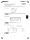
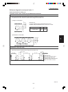
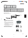
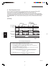
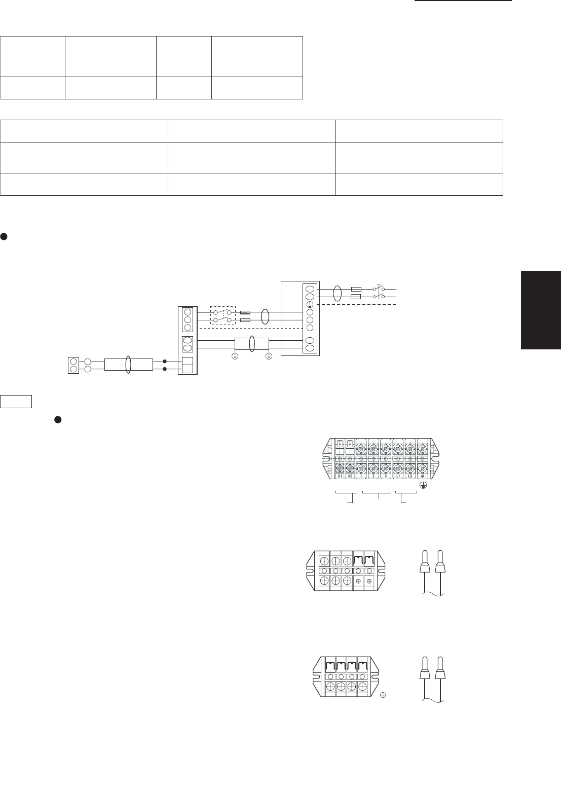
Wiring System Diagrams
Basic wiring diagram for standard control
NOTE
1) Refer to “ Recommended Wire Length and Wire
Diameter for Power Supply System” for the explana-
tion of “A”, “B”, “C”, “D”, and “E”, in the above dia-
grams.
2) Inter-Unit Control Wiring (C) and remote controller
wiring (D), (E) have no polarity. But for other wiring,
respect polarity. Be sure to connect as shown in the
Wiring System Diagram.
3) In case of separate supply connection to indoor unit,
over current protection must be provided between
power source and indoor unit.
MAXIMUM OVER CURRENT PROTECTION 15 A
(FUSE OR HACRTYPE CIRCUIT BREAKER)
U2
U1
L1
L2
U1
U2
1
2
G
2
1
WHT
Remote
controller
D
A
Indoor
unit
B
L1
L2
Grounding line
BLK
2
1
Inter-unit power line
208 / 230 V, 60 Hz
Power supply
208 / 230 V, 60Hz
Grounding line
C
Ground
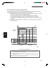
Outdoor unit
INV unit
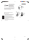
1
2
G
G
Inter-unit
power wiring
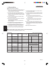
U1
Inter-unit
control wiring
U2
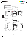
5P
terminal board
X, T, U Type
Remote
controller wiring
Inter-unit
control wiring
4P
terminal board
G
Inter-unit
power wiring
U1 U2
K Type
Inter-unit
power wiring
Power wiringInter-unit
control wiring
8P terminal board
CH Type
U1 U2
L2
1
2
G
L1
1
2
Remote
controller wiring
1
2