


– 24 –
SM830079
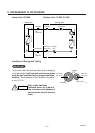
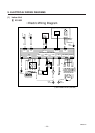
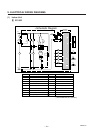
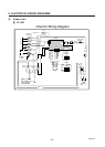
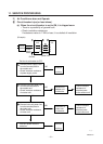
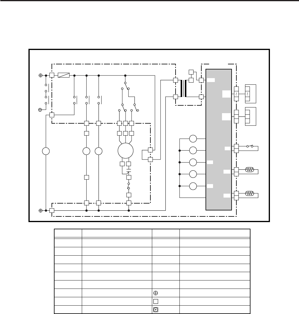
9. ELECTRICAL WIRING DIAGRAMS
(1) Indoor Unit
11
11
1 XS1852
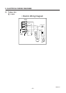
• Schematic Diagram
S 854-2-5268-872-00-0 (XS1852)
2
1
3
1
3
1
2
IND
3
1
2
7
1
7
1
SW
TR1
PRY
Coil
TH1
2
1
Room
TH2
FS
CR-TS2432
Controller
1
3
5
F1
(3A)
1
2
1
3
DP
RY2
RY1
RY3
RY4
RY5
3
2
LMPR
1
1
RY5
4P-3
4P-2
4P-1
1
FMI
12
1
9
8
735
456
RY1
RY2
RY2
HLM
1
3
49FMI
RY3
RY4
PRPR
Symbols Description
FMI
49FI
RC1
F1
DP
LM
TR1
PR
RY1-RY5
Indoor Fan Motor
Indoor Motor Thermal Protector
Running Capacitor
Fuse
Drain Pump
Auto Louver Motor
Power Transformer
Power Relay
Auxiliary Relay
Symbols Description
FS
TH1
TH2
CR-TS2432
IND
SW
Float Switch
Thermistor (Indoor Coil)
Room Thermistor
Indoor Controller
Indicator Lamp Assy
Switch Assy
Terminal Plate
Connector
Terminal
SEC
LM
TH1
TH2
DP
49FI
RC1
1
2
2
FS
W/
LESS
SW
ASSY