


– 21 –
SM830079
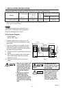
7. INSTALLATION INSTRUCTIONS
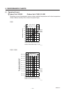
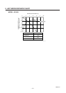
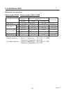
Recommended Wire Length and Wire Diameter for Power Supply System
AWG #12 AWG #12
C1852, CL1852 75 ft. 65 ft. 15 A 20 A AWG #12
Models
Time Delay
Fuse or
Circuit
Capacity
(B)
*1
Inter-unit
Wiring
(A)
*1
Power Supply
*1 Refer to the Wiring System Diagrams (See below diagram) for the meaning of “A”, “B”.
AWG = American Wire Gauge
Max. Wire
Diameter
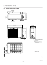
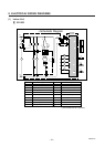
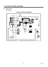
Power Supply Terminal Base
(Outdoor Unit)
Capacity
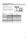
To access the electrical component box,
open the air intake grille and remove the
electrical component box cover.
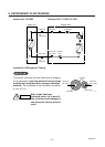
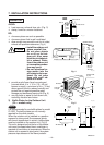
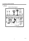
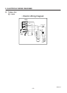
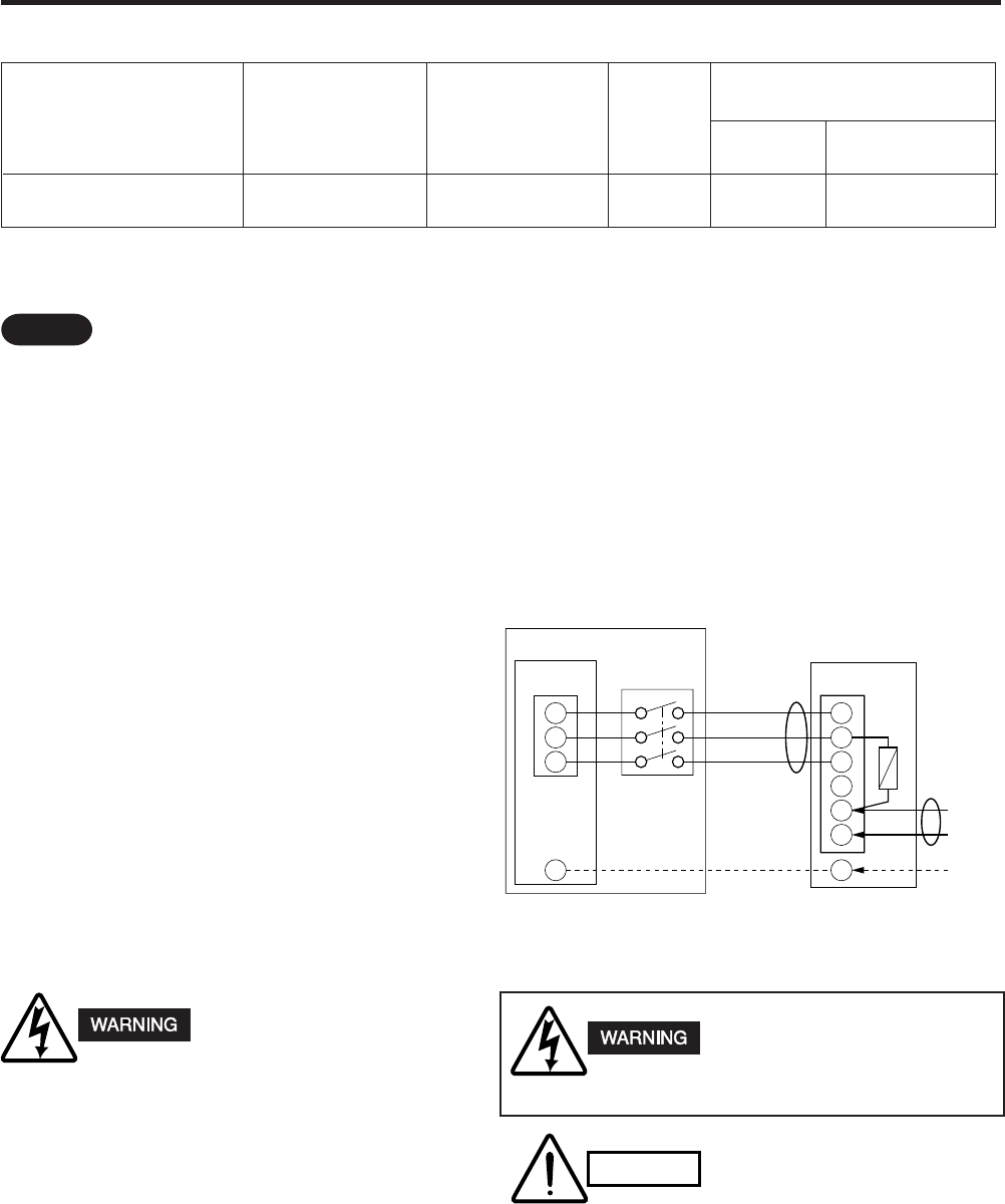
Wiring System Diagram
Single-phase
60 Hz, 230 / 208 V
NOTE
Conduit's trade size for this unit is 1/2".
The conduit can be purchased at a hard-
ware store.
The fuse located in the outdoor unit pro-
vides power supply protection and may
blow when power is applied if the system
has been incorrectly wired.
(1) Ground the unit in accordance with local
codes.
(2) Be sure to size each wire allowing sev-
eral inches longer than the required
length for wiring.
(3) Use lock nuts to secure the conduit
tubes.
1823_M_I
2
1
3
2
1
3
4
5
6
G
G
(Inter-unit)
Power lines
B
230/208 V
230/208 V
230/208 V
INDOOR
OUTDOOR UNIT
INDOOR UNIT
Disconnect
switch
(Field supply)
Grounding
line
Fuse
L1
L2
Power supply line
Single-phase, 230/208 V
A
Fig. 7
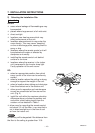
Be sure to comply with
local codes while run-
ning the wire from the
indoor unit to the out-
door unit (size of wire
and wiring method,
etc.).
Every wire must be
connected firmly.
No wire should be
allowed to touch refrig-
erant tubing, the com-
pressor or any moving
part.
To avoid the risk of
electric shock, each air
conditioner unit must
be grounded.
Be sure to connect the
power supply line to
the outdoor unit as
shown in the wiring
diagram. The indoor
unit draws its power
from the outdoor unit.
CAUTION