6. A.) For 3600/4600 “GHBO,” “GHB,” and “BHB” pumps with shaft packing, follow steps 7 – 18.
B.) For 3700/4700 “GHBO,” “GHB,” and “BHB” pumps with a standard mechanical seal, follow steps 28 – 38.
C.) For 3700/4700 “GHBO,” “GHB,” and “BHB” pumps with a positive drive mechanical seal, follow steps 39 – 53.
3600/4600 “GHBO” and “BHB” Pumps (See Figure 7.1)
7. Place drive gear (34) into case bore. Install key (B) in keyway of drive shaft (32). Slide drive shaft into bore of
drive gear.
8. Place appropriate number of case gaskets (20) on backplate side of case (19A, B, C, D). Align backplate (6A, B)
on dowel pins (J). Secure backplate to case using two washer head cap screws (K) and eight hex head cap
screws (L).
9. Install packing washer (18) over drive shaft (32) into packing bore of backplate.
10. Install packing rings (16) and lantern ring (17), if used, in packing bore of backplate. Stagger joints on each ring
180° apart. Seat each ring before adding next ring. Rings must not be tamped or seated too tightly.
11. Check drive shaft (32) for free movement after each ring is installed.
12. When packing box is sufficiently full to allow entry of packing gland (14) about ¼ of an inch [6 mm], reassemble
packing gland.
13. Place one square head bolt (G) through each slot in backplate (6A, B) and through each hole in packing gland
(14). Install packing gland (14) into packing box about ¼ of an inch [6 mm]. Slide packing gland clip (13) over
square head bolts (G). Using two locknuts (F), secure packing gland (14) in place. Install spring clip (15) across
square head bolts (G). Draw locknuts up evenly on packing to assure proper
seating of packing (16), then loosen
locknuts about ½ turn. DO NOT cock packing gland. This could cause binding or heating of drive shaft.
14. Install lip seal (5) in backplate (6A, B).
15. Install retaining ring (4) on drive shaft (32).
16. Install ball bearing (2) on drive shaft (32) and into backplate (6A, B) using retaining ring (3) to secure ball bearing
(2) in place as shown in sectional drawing Figure 7.1. The fit between the drive shaft and ball bearing may be a
light press fit.
17. Install spacer (47).
18. A.) For 3600/4600 “GHB” gear reduction unit, follow steps 39 – 47.
B.) For 3600/4600 “BHB” hydraulic drive assembly, go to Section 5, INSTRUCTIONS FOR ASSEMBLY OF A
TYPE “BHB” HYDRAULIC DRIVE, in the following pages.
3600/4600 “GHB” Gear Reduction Unit (See Figures 7.1 and 7.2)
19. Install cover gasket (50) and cover (49) on backplate (6A, B) using four socket head cap screws (AD).
20. Install key (Z) in keyway of drive shaft (32). Place drive gear (46) on drive shaft (32). Secure in place using
retaining ring (45).
21. Install needle bearing (43). The needle bearing is a press fit bore.
22. Install gear case (44) and gear case gasket (48) using six hex head cap screws (W), twelve flat washers (X), and
six lockwashers (Y).
23. Press ball bearing (41) onto pinion shaft (42) and install retaining ring (40).
24. Install pinion shaft assembly by sliding small end of pinion shaft into needle bearing (43) at same time gears are
meshed together.
25. Slide bearing retainer (37) assembled with lip seal (39) and bearing retainer gasket (38) into place. Secure
bearing retainer (37) to gear case (44) using four hex head cap screws (U) and four lockwashers (V).
26. Install drive key (A).
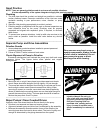
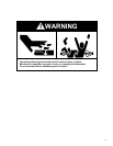
27. Read and understand all safety instructions and warnings before installing and operating pump.
10


