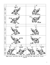
50. Remove drive gear (46). A gear puller may be necessary in removing gear, as a close fit is maintained between
gear and shaft.
51. Remove drive gear key (Z).
52. Remove four socket head cap screws (AD) securing cover (49) to backplate (6A, B). Remove cover gasket (50).
53. Remove spacer (47).
3700/4700 “GHBO” and “BHB” Pumps (See Figure 7.1)
54. Remove retaining ring (3) securing ball bearing (2) in place.
55. Remove drive shaft (32) along with ball bearing (2) and retaining ring (4) from backplate (6A, B).
56. Remove ball bearing (2) from drive shaft (32).
57. Remove retaining ring (4) from drive shaft (32).
58. If lip seal (5) is damaged or worn, remove from backplate (6A, B) and discard.
59. Remove two locknuts (F) from square head bolts (G) securing seal retainer (9) to backplate (6A, B). Remove seal
retainer (9).
60. When removing following type of single seals (John Crane
Type 21, Type 8-1, Type 9; Pac-Seal
Type 21;
Sealol
Type 43), clean and lubricate drive shaft (32) prior to removing mechanical seal making sure that drive
shaft is smooth and free from all burrs. Loosen setscrew (if present) on mechanical seal. Remove mechanical
seal (11). Inspect sealing surfaces of stationary seal face and inspect rotating element. Replace as required.
Remove retaining ring (12) from drive shaft (32), if applicable.
61. Visually inspect all parts. Replace all worn or damaged parts before reassembling pump. It is recommended that
new gaskets (20, 22, 25, if applicable) and new lip seals (5, 39) be installed each time pump is disassembled and
reassembled.
John Crane
is a registered trademark of John Crane Inc.
Pac-Seal
is a registered trademark of Pac-Seal Inc.
Sealol
is a registered trademark of EG & G Sealol.
3. INSTRUCTIONS FOR PUMP ASSEMBLY
Refer to Section 7, PARTS LIST, (Figures 7.1 and 7.2).
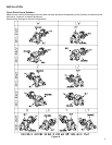
Refer to Section titled “Check Ports Versus Rotation” (Figures A and B) to assure proper configuration for pump rotation,
port location, and relief valve position prior to assembling pump.
1. Visually inspect all parts during assembly. Replace all worn or damaged parts. Although they may appear
reusable, it is recommended that new gaskets (20, 22, 25, if applicable, 38, 48, 50) and lip seals (5, 39) be
installed when pump is being reassembled.
• WARNING! Only use genuine Roper gaskets. Gasket thickness determines proper clearances. Always check
quantity of gaskets removed and replace with exact quantity. Proper material must be used based on application.
2. When cleaning or lubricating, only use products that are compatible with product being pumped and elastomers
within pump. DO NOT use petroleum base products with seals with EPR elastomers. Clean and lubricate parts
with light oil unless EPR elastomers are used. Use a nonpetroleum base lubricant with EPR elastomers.
3. Mechanical seals are precision pieces of equipment. Use extreme care not to damage seal faces or elastomers
during assembly.
4. Install two hollow dowel pins (J) on each side of case (19A, B, C, D). Place appropriate number of case gaskets
(20) on faceplate side of case. Align faceplate (23A, B, C) on hollow dowel pins (J). Secure faceplate to case
using two washer head cap screws (K) and eight hex head cap screws (L).
5. Place idler gear (35) into case bore. Install key (B) in keyway on idler shaft (33). Slide idler shaft into I.D. of idler
gear.
9


