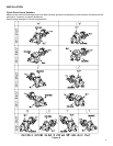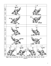
50. Install antirotation pin (T) in locator ring (60).
51. Position locator ring (60) with antirotation pin (T) toward seal face. Align antirotation pin (T) with slot in back of
stationary seal face and push into counterbore of backplate (6A, B).
52. Place one square head bolt (G) through each hole in seal retainer (9). Secure seal retainer against backplate
using two locknuts (F).
53. A.) For 3700/4700 “GHB” gear reduction unit, follow steps 19 – 27.
B.) For 3700/4700 “BHB” hydraulic drive assembly, go to Section 5, INSTRUCTIONS FOR ASSEMBLY OF A
TYPE “BHB” HYDRAULIC DRIVE.
4. INSTRUCTIONS FOR DISASSEMBLY OF A TYPE “BHB”
HYDRAULIC DRIVE
Refer to Section 7, PARTS LIST.
1. Read WARNINGS before starting to disassemble hydraulic drive components from pump. While disassembling,
always inspect disassembled parts and adjacent parts to see if further disassembly is needed. Replace worn or
damaged parts as required.
2. Turn off pump and lock out energy source to hydraulic motor. DO NOT proceed further with disassembly of pump
if there is the slightest possibility that hydraulic motor may be started.
3. Close inlet and discharge valves.
4. If pump is to be disassembled:
A.) Refer to pump sectional drawing for “GHBFORV”.
B.) If used, turn off and disconnect flush for packing or mechanical seal.
C.) Follow the procedures in the Owners Manual for 3611-22 (G12-209), INSTRUCTIONS FOR
DRAINING PUMP.
D.) Disconnect lines from pump inlet and discharge.
5. Remove six socket head cap screws (AE) and six lockwashers (AF) that secure bracket (51) and bracket (52)
together. Slide apart.
6. Remove cap screws that secure hydraulic motor to bracket (52).
7. Rotate bracket (52) until hole for loosening setscrew lines up with setscrew in coupling half (54). Loosen setscrew
and remove coupling half.
8. Remove coupling spider (55).
9. Rotate drive shaft of pump (32) until setscrew in coupling half (53) lines up with hole for loosening setscrew.
Loosen setscrew. Remove retaining ring (45) from drive shaft and remove coupling half.
10. Remove drive key (Z).
11. Remove four socket head cap screws (AD) that secure bracket (51) to backplate (6A, B). Remove bracket.
12. For further disassembly of the pump, refer to Section 2, INSTRUCTIONS FOR PUMP DISASSEMBLY,
steps 1 – 20. Also, refer to steps 33 – 41 for pumps with packing, or steps 54 – 61 for pumps with mechanical
seals.
12


