


ELECTRICAL CONNECTIONS
C;tlt?ck wrth your local L,tillties for eiectrical codes that apply
in your area. If there are no local codes, the National
Eilecirical Code, ANSI/NFPA No 70-I 990 must be followed.
You can get a copy by tiriting:
National Fire Protection Association
Ba?terymarch Park
Qumy, MA 02269
A:I &equate electrical supply and outlet must be used to
opt rate the electrical parts of your oven. The oven cord has
a ttiree prong plug and must be used with a properly
gro Jnded three hole outlet with standard 120 volt, 60 Hertz
AC household current
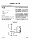
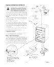
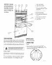
install the electncar outlet below the oven on the right side.
It sl~ould be easily reached through cabinet doors below the
oven
see Figure 5. A llole must be made In the cabinet for
the electrlcal hook-up
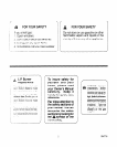
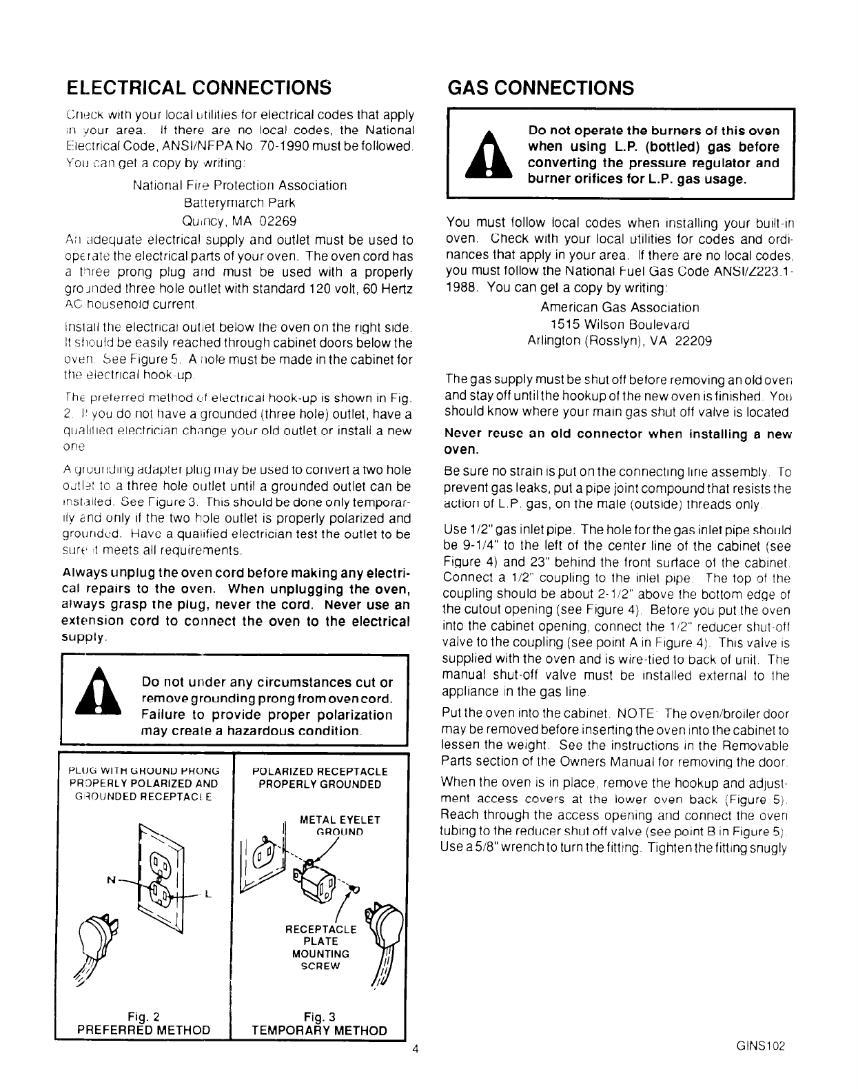
iht preterred method c;f electrlcal hook-up is shown in Fig.
2 I! you do not have a grounded (three hole) outlet, have a
qualiilea electricjan change your old outlet or install a new
0 n e
A qroundlng adapter plug may be used to convert a two hole
o~tl?l to a three hole outlet until a grounded outlet can be
tnst,lllea. See Figure 3. rh1.s should be done only temporar-
11y and only of the two hole outlet is properly polarized and
grounded. Have a qualified electrician test the outlet to be
surf’ ! meets all requirements.
Always unplug the oven cord before making any electri-
cal repairs to the oven. When unplugging the oven,
always grasp the plug, never the cord. Never use an
extension cord to connect the oven to the electrical
supply.
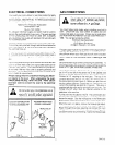
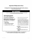
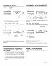
Do not under any circumstances cut or
removegroundingprongfromovencord.
Failure to provide proper polarization
may create a hazardous condition.
PLIJG
WITH GROUND PRONG
POLARIZED RECEPTACLE
PROPERLY POLARIZED AND
PROPERLY GROUNDED
G’3OIJNDED RECEPTACI E
METAL EYELET
RECEPTACLE
Fig. 2 Fig. 3
PREFERRED METHOD
TEMPORARY METHOD
4
GAS CONNECTIONS
Do not operate the burners of this oven
I
when using L.P. (bottled) gas before
converting the pressure regulator and
burner orifices for L.P. gas usage.
You must follow local codes when installing your built-in
oven. Check with your local utilities for codes and ordl-
nances that apply in your area. If there are no local codes,
you must follow the National Fuel Gas Code ANSl/Z223.1-
1988. You can get a copy by writing:
American Gas Association
1515 Wilson Boulevard
Arlington (Rosslyn), VA 22209
The gas supply must be shut off before removing an old over;
and stay off until the hookup of the new oven is finished. You
should know where your main gas shut off valve is located
Never reuse an old connector when installing a new
oven.
Be sure no strain is put on the connecting line assembly
To
prevent gas leaks, put a pipe joint compound that resists the
action of L.P. gas, on the male (outside) threads only
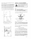
Use 1/2”gas inlet pipe. The hole forthe gas inlet pipe should
be 9-114” to the left of the center line of the cabinet (see
Figure 4) and 23” behind the front surface of the cabinet
Connect a 112” coupling to the inlet pipe The top of the
coupling should be about 2-112” above the bottom edge of
the cutout opening (see Figure 4)
Before you put Ihe oven
into the cabinet opening, connect the 1’2” reducer shut-off
valve to the coupling (see point A in Figure 4). This valve
IS
supplied with the oven and is wire-tied to back of unit. The
manual shut-off valve must be Installed external to the
appliance in the gas line.
Put the oven into the cabinet. NOTE
The oven/broiler door
may be removed before inserting the oven rnto the cabinet to
lessen the weight. See the instructions In the Removable
Parts section of the Owners Manual for removing the door
When the oven is in place, remove the hookup and adjust-
ment access covers at the lower oven back (Figure 5)
Reach through the access opening and connect the oven
tubing to the reducer shut off valve (see point B in Figure 5)
Use a 518” wrench to turn the fitting
Tighten the fitting snugly
GINS1 02