6. Mark placement of mounting holes (see Figure 3). Set base aside.
7. Drill the marked holes using a 3/16” (5mm) drill bit. NOTE: Enclosed
plastic anchors do not require a drilled hole for drywall.
8. Tap plastic anchors into the wall.
9. Align base with plastic anchors and feed wires through opening (see
Figure 3).
10. Secure base to wall with supplied screws.
11. Connect wires to terminal strip. Refer to wiring diagrams on page 5.
Make sure wire connections are secure.
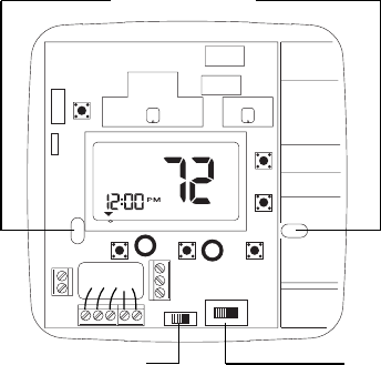
12. Place Electric/Gas switch into either the ELEC or GAS position
depending on the type of furnace (see Figure 3).
13. Place the HP option switch into either the NON_HP or HP position
depending on the type of system you are using (see Figure 3). Use
the HP position for heat pumps ONLY. Use the NON_HP setting for
everything else.
14. Replace cover on thermostat by snapping into place.
15. Turn on power to system. Test thermostat as described in the
section To Test Thermostat.
4
MON
°
F
R
L
C
Y2
W2/E
GOBY1W1
Mounting Holes
ELECTRIC/GAS SWITCH
Selects fan control.
HP OPTION SWITCH
Heat pump switch.
Figure 3
110-1101B 3/4/05 3:56 PM Page 4


