


TABLE OF FIGURES
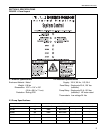
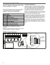
Figure 1: Panel Layout ..............................................................3
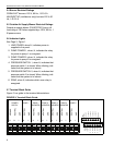
Figure 2: Terminal Block Guide.................................................4
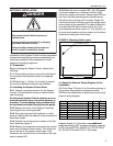
Figure 3: Mounting Hole Layout................................................5
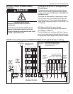
Figure 4: System Configuration.................................................6
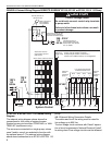
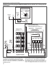
Figure 5: External Wiring Diagram ROBERTS GORDON
®
EP-100 and EP-201 120 V 1 Ø Pump ........................7
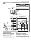
Figure 6: External Wiring Diagram ROBERTS GORDON
®
EP-100, EP-201 or EP-301, 230 V 1 Ø Pump ............8
Figure 7: External Wiring Diagram ROBERTS GORDON
®
EP-203 or EP-303, 208 - 230 V (or 460 V)
3 Ø Pump...................................................................9
Figure 8: External Wiring Diagram ROBERTS GORDON
®
EP-100 or EP-201 120 V 1 Ø Pump with Outside
Air Blower ................................................................10
Figure 9: System Control Troubleshooting Chart ....................13
Figure 10: System Control Internal Components Diagram......14