


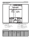
SECTION 3: INSTALLATION
5
SECTION 3: INSTALLATION
Installation of the System Control and the associated
external electrical wiring must be completed by an
electrician qualified in the installation of control
systems for heating equipment.
3.1 Preparation
Before installing the System Control, observe the
following:
3.1.1 Ensure that you have a copy of the site layout
for the project that identifies clearly the separate
zones.
3.1.2 Read Page 1, Section 1.4 carefully to ensure
the correct installation materials are available.
3.2 Installing the System Control Panel
3.2.1 Choose a mounting location for the System
Control. It is advisable to choose a visible location
near the pump.
Do not mount System Control outdoors or in an
area with moisture spray, excessive moisture or
humidity. To avoid damage from possible drips,
do not mount controller directly beneath pump.
3.2.2 Remove the cover of the System Control by
removing the four securing screws.
3.2.3 Place the cover and the hardware in a safe
place for refitting after the external wiring connections
have been made.
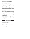
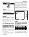
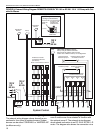
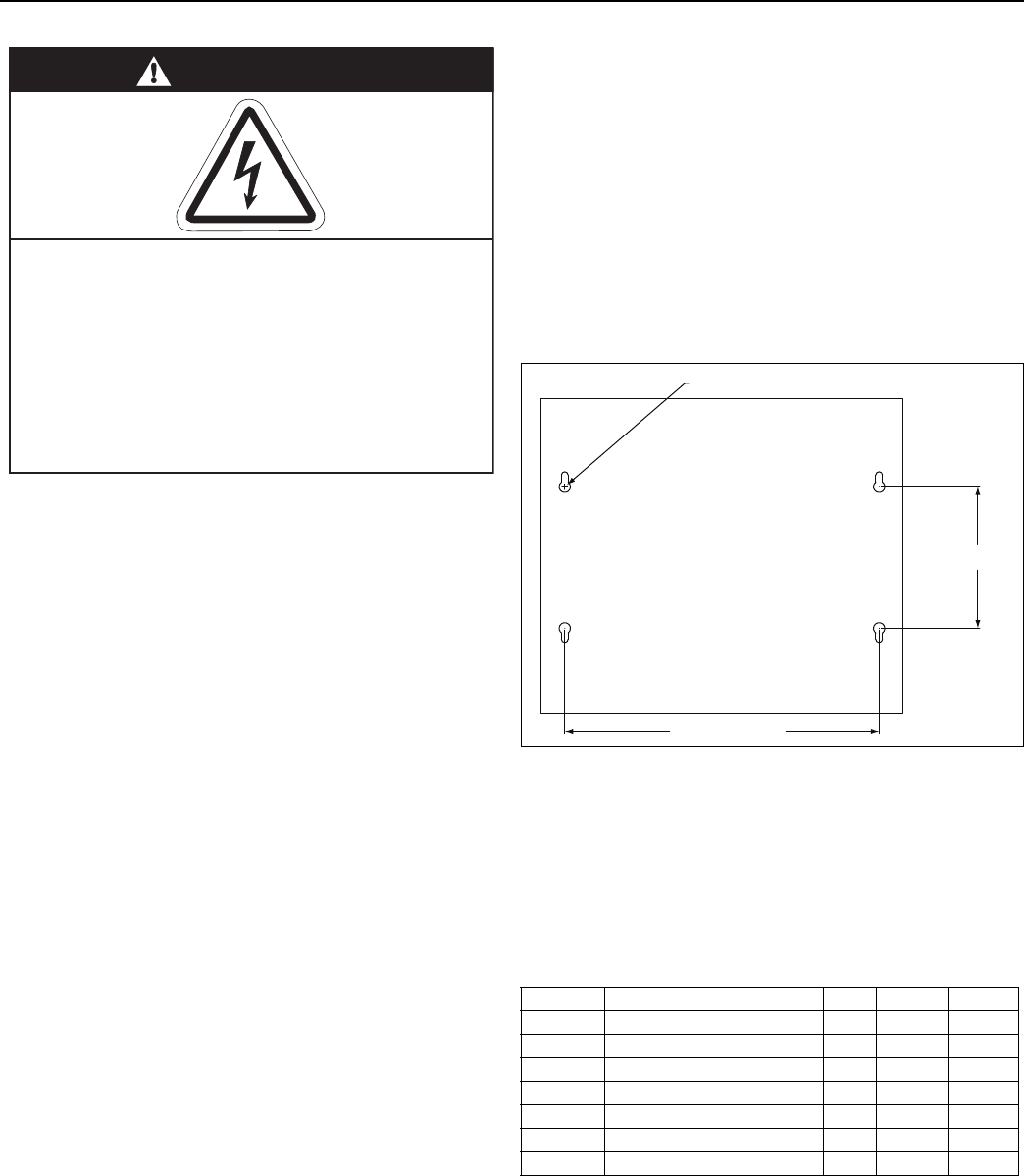
3.2.4 Position the mounting hole location of the Sys-
tem Control per Figure 3.
3.2.5 Remo
ve the knockouts required for the conduit
entry into the System Control panel. The knockouts
are on the top of the system control case. If the
knockouts are required to be on the bottom the case
can be rotated 180°.
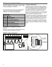
3.2.6 When the case is rotated 180°, the LED status
circuit card needs to be rotated so that the LED's
match the upright cover panel. Remove the LED sta-
tus circuit card by squeezing each standoff gently
with pliers one at a time until it is loose. Rotate the
circuit card so that it will line up with the upright cover
and re-attach to the standoffs. The ribbon cable that
connects the LED status circuit card to the circuit
card assembly will have a twist in it. Use caution not
to cause any creases or put any tension to the ribbon
cable when rotating the circuit card.
FIGURE 3: Mounting Hole Layout
3.3 Select the External Wiring Diagram for the
Installation
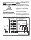
3.3.1 Use Page 7, Section 4 for the external wiring of
the burners, thermostats and press
ure switch.
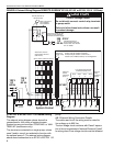
3.3.2 Use the table below to select the correct pump
external wiring diagram.
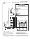
Roberts-Gordon LLC provides, at an additional
cost, the following IEC contactor packages required
for EP-100 and EP-201 208/230 V (1 Ø), EP-203 (3
Ø), EP-303 (3 Ø) and EP-301 (1 Ø) pumps.
DANGER
Electrical Shock Hazard
Disconnect electric before service or
maintenance.
Control must be connected to a properly
grounded electrical source.
Failure to follow these instructions can
result in death or electrical shock.
Pump Supply VoltagePageSectionFigure
EP-100 120 V 1 Ø 7 4 5
EP-100 208/230 V 1 Ø 8 4 6
EP-201 120 V 1 Ø 7 4 5
EP-201 208/230 V 1 Ø 8 4 6
EP-301 120/208 - 230 V 1 Ø 8 4 6
EP-203 208 - 230 V (or 460 V) 3 Ø 9 4 7
EP-303 208 - 230 V (or 460 V) 3 Ø 9 4 7
10.0" (254 mm)
4.5" (114 mm)
4 x Ø 0.360" (9 mm)