


BLACKHEAT
®
HE INSTALLATION OPERATION AND SERVICE MANUAL
58 of 73
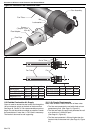
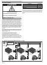
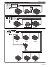
14.1.2 Heater Lockout Indicator by Volt Free
Connector
A volt free contact relay is closed which enables the
ROBERTS GORDON
®
controller, BMS system, etc. to
indicate the heater that has failed. An additional wire has
to be installed from the heater volt free connector to the
monitoring computer. See Page 56, Section 13.5.
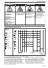
14.2 Testing
Establish that a satisfactory purged gas supply and an
electrical supply is available to the heater. Ensure that all
time clocks and thermostats are set to call for heat.
With the gas supply cut off and the electrical supply
isolated by switching off at the local switch, open the
control chamber secured by the screws. Loosen the
sealing screw from the pressure test point and remove
the cover cap from the governor.
Turn on the gas supply and connect appliance electrical
plug. Ensure that the timer or thermostat, if fitted, are set
to call for full gas rate. Switch on at the local switch. The
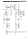
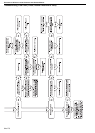
sequence as described should take place. If not, refer to
detailed fault finding sequence. When flame is
established, check the gas pressure reading and adjust if
necessary. Refer to burner data label.
Check the gas pressure at the outlet of the gas valve. See
Page 73, Section 18.9.1 for pressure settings or refer to
the data plate.
Switch off the electrical supply (shutting down the heater),
remove pressure gauge, tighten pressure test point
screw, ensuring a tight gas seal. Replace governor cover
cap. Replace control chamber door.
14.3 Commissioning (Multiburner)
1. Establish that a satisfactory purged gas supply and
an electrical supply is available to the heater.
2. ENSURE that all the dampers are in the fully open
position.
3. With the gas supply off at each of the burners and
the electrical supply isolated, open the control
chamber secured by six screws.
4. Ensure that all time clocks and thermostats are set
to call for heat.
5. Switch on the electrical supply at the main isolator.
This will start the exhaust fan.
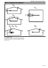
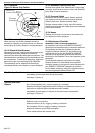
6. Balancing Cold Suction
Check each burner vacuum by connecting an
inclined pressure gauge to the tee on the pressure
switch inlet side in the burner. Adjust the damper so
that the suction is 1.9 mbar. Repeat for each burner.
7. Start at the end burner (furthest from the exhaust
fan) with the inclined pressure gauge connected as
described above. Turn on the gas and electrical sup-
ply, reset the pressure switch by removing suction
from the inlet side of the pressure switch waiting
several seconds and reconnecting. The start up
sequence described on Page 57, Section 14 should
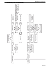
take place. If not, refer to detailed fault finding
sequence. When flame is established, check the
gas pressure reading and adjust if necessary. See
data label.
Check the gas pressure at the outlet of the gas
valve. See Page 73, Section 18.9.1 for pressure set-
tings or refer to the data plate.
Switch off the electrical supply (shutting down the
heater), remove pressure gauge, refit pressure test-
point screw, ensuring a tight gas seal. Replace gov-
ernor cover cap.
Repeat this procedure for each burner in the sys-
tem.
Close the control chamber and secure with six
screws.
8. Balancing Hot Suction
Reconnect all the burners on the system and allow
them to reach full operating temperature (approxi-
mately 20 minutes). Return to each burner and
recheck the hot suctions at the tee on the inlet to the
pressure switch. Re-adjust the damper so that the
hot suction of 1.7 mbar is achieved and lock the
damper in position.
14.4 System Checks
Switch on again at the local switch to help ensure smooth
ignition. Carry out the following system checks:
When running, turn off the gas supply at the appliance.
The heater will immediately shut down followed by one
attempt at restoration followed by lockout.
Linear and Double Linear only:
When running, disconnect the fan plug from the burner.
The unit should shut down within three seconds, proving
operation of the pressure switch.
14.5 User Instructions
After satisfactory testing, ensure that the client is fully
aware of the operation of the system. Bring this manual to
the attention of the user or purchaser; instruct them in the
safe operation of the heater(s).
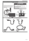
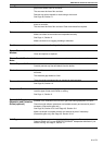
Description Part Number
Connector male - Lockout Indicator 91324000
Connector female - Lockout Indicator 91324001
Wire Blue 12" 91300011
Wire Brown 12" 91300012
Description Part Number
Connector male - Volt Free 91324000
Connector female - Volt Free 91324001
Wire Blue 7" 91300004
Wire Brown 7" 91300005
Wire Yellow 12" 91300003
Screw #8 x 3/8 Hex Wshr PHH Type 23 94961406
Base relay P2RF05E C1050B
Relay G2R1-SN IMO 220 V 10 A C1049B