


SECTION 14: OPERATION
57 of 73
SECTION 14: OPERATION
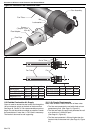
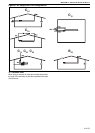
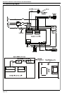
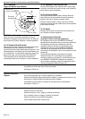
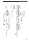
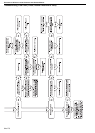
Figure 33: Sequence of Operation Chart
NOTE: If the heater operates for more than 24 hours continuously, the ignition module will automatically recycle the
burner to ensure that all safety functions are still in working condition.
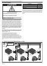
14.1 Heater Lockout Indication (Optional)
In case of flame loss during operation of the heater, the
burner control unit goes to lockout mode after three
ignition trials. At this stage a signal or closed relay will
enable the ROBERTS GORDON
®
controller, BMS
system, etc. to indicate precisely which heater has failed.
This can be done by two options.
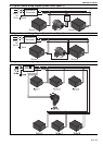
14.1.1 Heater Lockout Indicator by Connector
A 230 V signal is provided which enables the ROBERTS
GORDON
®
controller, BMS system, etc. to indicate the
heater that has failed. An additional wire has to be
installed from the heater lockout indicator connector to
the monitoring computer. See Page 56, Section 13.5.
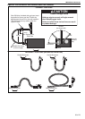
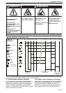
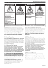
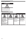
Cut/Pinch Hazard
Wear protective gear
during installation,
operation and service.
Edges are sharp.
WARNING
Failure to follow these instructions can result in death, electric shock, injury or property damage.
Burn Hazard
Allow heater to cool
before service.
Tubing may still be hot
after operation.
Explosion Hazard
Turn off gas supply to
heater before service.
DANGER
Electrical Shock Hazard
Disconnect electric
before service.
More than one
disconnect switch may
be required to
disconnect electric from
heater.
Heater must be
connected to a properly
grounded electrical
source.
P
P
Fan Neon
Burner Neon
Neon
Ignition
Gas
Valve
Flame
Sensing
Pressure
Switch
Fan
Thermostat
KEY TO
SYMBOLS
T0 T1 T2 T3 T4 T5 T6 T7
10 sec
Tp
40 sec max.
Interruption of main
Tp
10 sec
Ts
10 sec
flame sensing
11 sec typical
T8
Lockout Alarm
Signal (optional)
Burner Lockout
signal received after
3 ignition trial
failures