


BLACKHEAT
®
HE INSTALLATION OPERATION AND SERVICE MANUAL
54 of 73
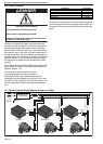
SECTION 13: WIRING
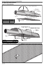
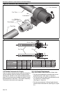
Connect to the electrical supply using the power wire
coming out of the wire gland via a locally mounted IP55
protected double pole fused switch having a minimum
disconnection of 3 mm on each pole. This switch should
be fused to 3 amps. There are no control connections in
the standard burner. Control is affected by interruption of
the main power inlet. See Page 54, Section 13.1 through
Page 55, Section 13.4 for the external wiring details for
the single-burner, double linear and multiburner heater
systems.
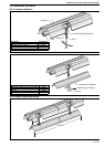
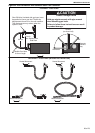
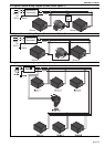
If the IP55 protected fan MB 56 2BM is used with a single
burner (linear or U-tube), it must be wired as shown on
Page 55, Section 13.2.
The fan must be protected with a 3 A fuse.
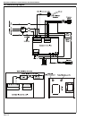
If the heater lockout indication is required, a
BLACKHEAT® HE lockout indicator package (P/N
03360008) must be installed in every burner. Drill a 20.5
mm hole to fit the wire gland. See Page 56, Section 13.5
for wire connections. Remove the taps from the power
wire.
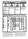
All wiring must comply with current wiring regulations and
any local regulations which may apply. Always switch off
the supply to the burner before removing the burner side
panel.
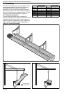
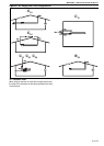
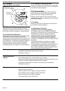
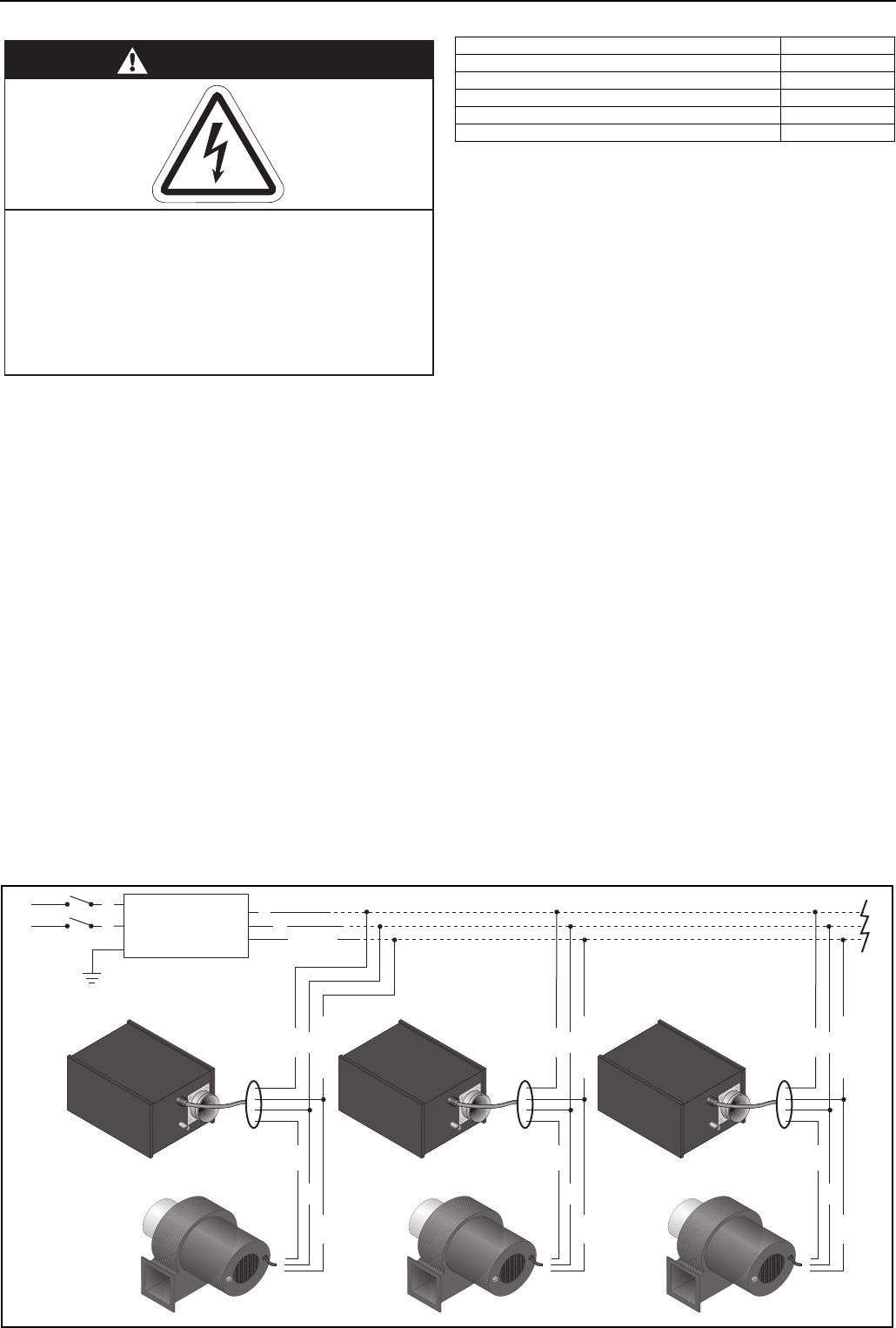
13.1 Typical External Wiring Diagram (Linear or U-Tube)
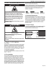
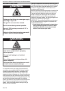
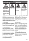
DANGER
Electrical Shock Hazard
Disconnect electric before service.
Heater must be properly grounded.
Failure to follow these instructions can result
in death or electrical shock.
Description Part Number
BLACKHEAT
®
HE Lockout Indicator Package
03360008
Cable Gland U169
Power Wire 91300010
Blue Wire 91300011
Brown Wire 91300012
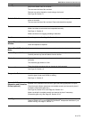
Burner 1
Fan 1
Earth
Burner 2
Fan 2
Burner 3
Fan 3
Controller or
Thermostat
230 V
1 Ø
50 Hz
L
N
Earth
N
L
Blue
Green
Black
Blue
Brown
Green/Yellow
4 Wire Cable
{
Blue
Green
Black
Blue
Brown
Green/Yellow
4 Wire Cable
{
Blue
Green
Black
Blue
Brown
Green/Yellow
4 Wire Cable
{