


BLACKHEAT
®
HE INSTALLATION OPERATION AND SERVICE MANUAL
10 of 73
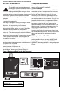
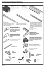
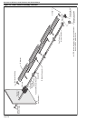
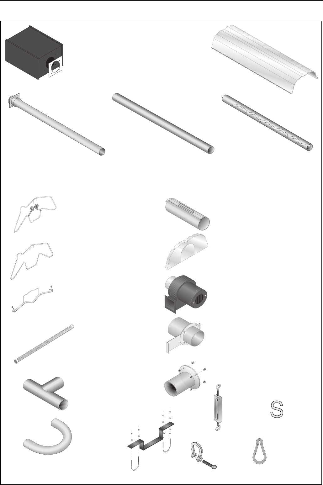
SECTION 4: MAJOR COMPONENT DESCRIPTIONS
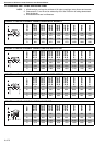
Burner (shown with Tube
Gasket)
Must be installed with the
flame observation window
facing down.
Reflector
(Aluminium or
Stainless Steel)
Alternate overlap as
shown on overview.
Minimum overlap is 160 mm.
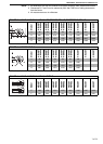
Coupling Assembly
with Lock
Reflector End Cap
Punch out center section to
accommodate tube.
Fan Assembly (Includes Flange)
Fan assembly is attached to the last
section of heat exchanger tubing
(fan tube).
Tube and Reflector Hanger
Suspend system from these
hangers.
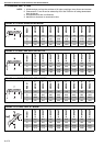
Flex Gas Line
Tube
Heat treated aluminised tube
supplied in 3000 mm lengths.
Burner Tube
Supplied in 3000 mm lengths.
Burner tube is always the first
tube after the burner.
Reflector Support Strap, Wire
Form & #8 x 3/4 Screw
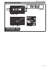
Fan Tube with Internal Swirler
Supplied in 3000 mm lengths. Fan
tube is always the last tube on the
heater where the fan is attached.
The swirler is welded inside of the
tube end.
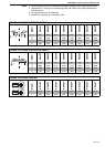
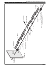
Fan Flange Assembly
and Screws
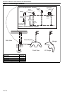
U-tube
Height
Adjuster
Bow
Shackle
Tee
Assembly
U-tube
Support
Bracket
Damper Flange Assembly
For use on Multiburner Systems.
Tube and Reflector Hanger
with Clamp Package
Position this hanger no more
than 100 mm away from the
burner assembly.
Spring
Hook
S-hook