


SECTION 7: VENTING
13
SECTION 7: VENTING
7.1 General Venting Requirements
Install the venting in accordance with the require-
ments within this manual and the National Fuel Gas
Code, ANSI Z223.1/NFPA-54 - latest revision and
CSA 22.1 - latest revision. This section provides par-
tial information about this specification with regard to
size and configuration for venting requirements (see
following figures). However, to provide assurance of
proper and safe operation, it is the responsibility of
the installer to make sure the installation is in strict
accordance with all local and national codes.
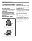
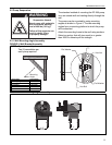
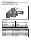
7.2 Venting the Pump
• The exhaust connection from the pump is 4.5"
(11 cm) diameter.
• Connect one of the flexible isolation boots pro-
vided to the 4" (10 cm) flue pipe, using the sili-
cone rubber ring provided.
• Connections to flue pipe larger than 4" (10 cm)
require use of an appropriate "taper pattern
reducer" (not supplied).
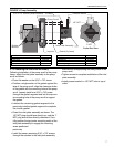
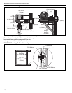
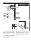
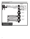
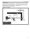
• Venting from the pump may discharge either hori-
zontally or vertically. Horizontal discharge is
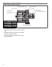
preferred. See Page 14, Figure 13. Vertical dis-
charge must be arranged as shown on Page 15,
Figure 14. Corrosion resistant pipe is required.
• Both horizontal and vertical venting must be sup-
ported by suitable hangers.
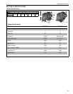
• Vent lengths are allowed as follows:
7.3 Horizontal Venting
The vent material must be either porcelain coated
tubing 4" (10 cm) O.D. (P/N 9141030D), heat treated
aluminized tubing 4" (10 cm) O.D. (P/N 91409408),
heat treated aluminized tubing 6"(15 cm) O.D. (P/N
E0009105) or single wall flue pipe minimum 26 Ga.
Vent length be limited to less than 30' (9 m). If using
vent lengths greater than 30' (9 m), condensation will
form in the vent pipe. Insulation and additional seal-
ing measures will be required.
7.3.1 Horizontal Venting Guidelines
• Vent must exit building not less than 7' (2 m)
above grade when located adjacent to public
walkways.
• Vent must terminate at least 3' (1 m) above any
forced air inlet located within 10' (3 m).
• Vent must terminate at least 4' (1.2 m) below 4'
(1.2 m) horizontally from or 12" (30 cm) above
any door, window or gravity air inlet into building.
• Locate vent terminal at least 12" (30 cm) from any
opening through which vent gases could enter a
building.
• Use only corrosion resistant materials for the
discharge line from the pump to the point of
discharge.
• Vent terminal opening must extend beyond any
combustible overhang.
• Install vent terminal at a height sufficient to pre-
vent blockage by snow.
• Protect building materials from degradation by
flue gases.
• Any portion of flue pipe passing through a com-
bustible wall must be dual insulated and an
approved thimble must be used.
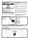
7.3.2 Side Wall Venting
Vent recommendations in order of preferred use:
1. Porcelain coated tubing 4" (10 cm) O.D. (P/N
9141030D)
2. Heat treated aluminized tubing 4" (10 cm) O.D.
(P/N 91409408)
Heat treated aluminized tubing 6" (15 cm) O.D.
(P/N E0009105)
3. Single wall flue pipe - minimum 26 ga.
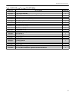
VENT LENGTH VENT SIZE
Up To 10' (3 m) 4" (10 cm) vent - 1 elbow
Up To 25' (8 m) 5" (12.5 cm) vent - 3 elbow
Up To 50' (15 m) 6" (15 cm) vent - 3 elbow
Carbon Monoxide Hazard
Pump must be vented to the
outside.
Heaters must be installed
according to the installation
manual.
Failure to follow these
instructions can result in death
or injury.
WARNING