


EP-200 SERIES PUMP INSTALLATION, OPERATION AND SERVICE MANUAL
6
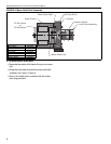
SECTION 5: PUMP INSTALLATION
5.1 Pump Assembly Instructions
5.1.1 Determine Orientation of Pump Discharge
To ensure your safety, and comply with the terms of
the warranty, all units must be installed in accor-
dance with these instructions.
The pump must be installed in a location that it is
readily accessible for servicing.
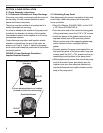
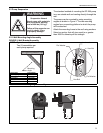
An arrow is affixed to the outside of the pump scroll
to indicate the direction of rotation of the impeller.
The standard rotation of the impeller is in the coun-
terclockwise direction.
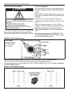
Pump discharge orientation and impeller rotation
direction is viewed from the rear of the motor as
shown in on Page 6, Figure 2. Note that the pump
scroll outlet must always be positioned at the bottom
horizontal position.
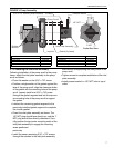
FIGURE 2: Pump Discharge Orientation /
Impeller Rotation Direction
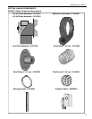
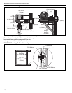
5.1.2 Attaching Pump Scroll
After determining the correct orientation of the pump
scroll outlet, attach the pump scroll to the pump
frame as follows:
• Place Flat Washer (P/N 95211600), on the 5/16"
x 7/8" Screw (P/N 94273914).
• From the motor side of the vertical mounting plate
of the pump frame, insert the 5/16" x 7/8" screws.
• Install two pieces of the gasket material on the
exposed thread ends of the mounting screws.
Make sure the ends of the opposing gasket seg-
ments interlock to form a complete circular
gasket.
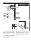
• Carefully position the pump scroll against the ver-
tical mounting plate of the pump frame; align and
loosely install the 5/16" x 7/8" screws into the cor-
responding mounting holes in the pump scroll.
• While tightening the screws that secure the pump
scroll to the motor frame, periodically spin the
impeller to be sure that adequete clearance is
maintained between the impeller blades and the
body of the pump scroll.
Arrow showing direction of rotation
(located on front of scroll housing)
Counterclockwise Rotation
(Standard)
OUTLET
Clockwise Rotation
OUTLET