


EP-200 SERIES PUMP INSTALLATION, OPERATION AND SERVICE MANUAL
12
SECTION 6: MOTOR WIRING
All wiring must comply with current wiring regulations
and any local regulations which may apply. Always
switch off the supply and disconnect before servicing.
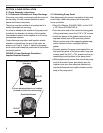
6.1 Prior to Operation
Prior to operation of the pump in the heating system,
operation and proper rotation of the impeller must be
verified.
IMPORTANT: Improper rotation of the impeller will
not produce the vacuum required for proper system
operation.
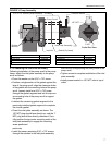
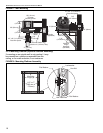
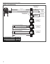
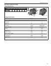
The EP-201 motor must be wired for clockwise or
counterclockwise rotation as shown on Page 12, Fig-
ure 11.
The EP-201 motor is wired for 1 Ø, 120 V, 60 Hz
operation. The EP-201 motor can be rewired for 230 V
operation by changing the motor connections as
indicated by the diagram on the motor connection box
cover.
Wire the pressure switch per the CORAYVAC
®
(P/N
127102NA), VANTAGE
®
EV (P/N 151100NA) or appro-
piate controller installation manual.
FIGURE 11: EP-201 Motor Wiring
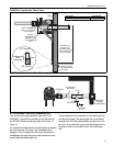
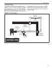
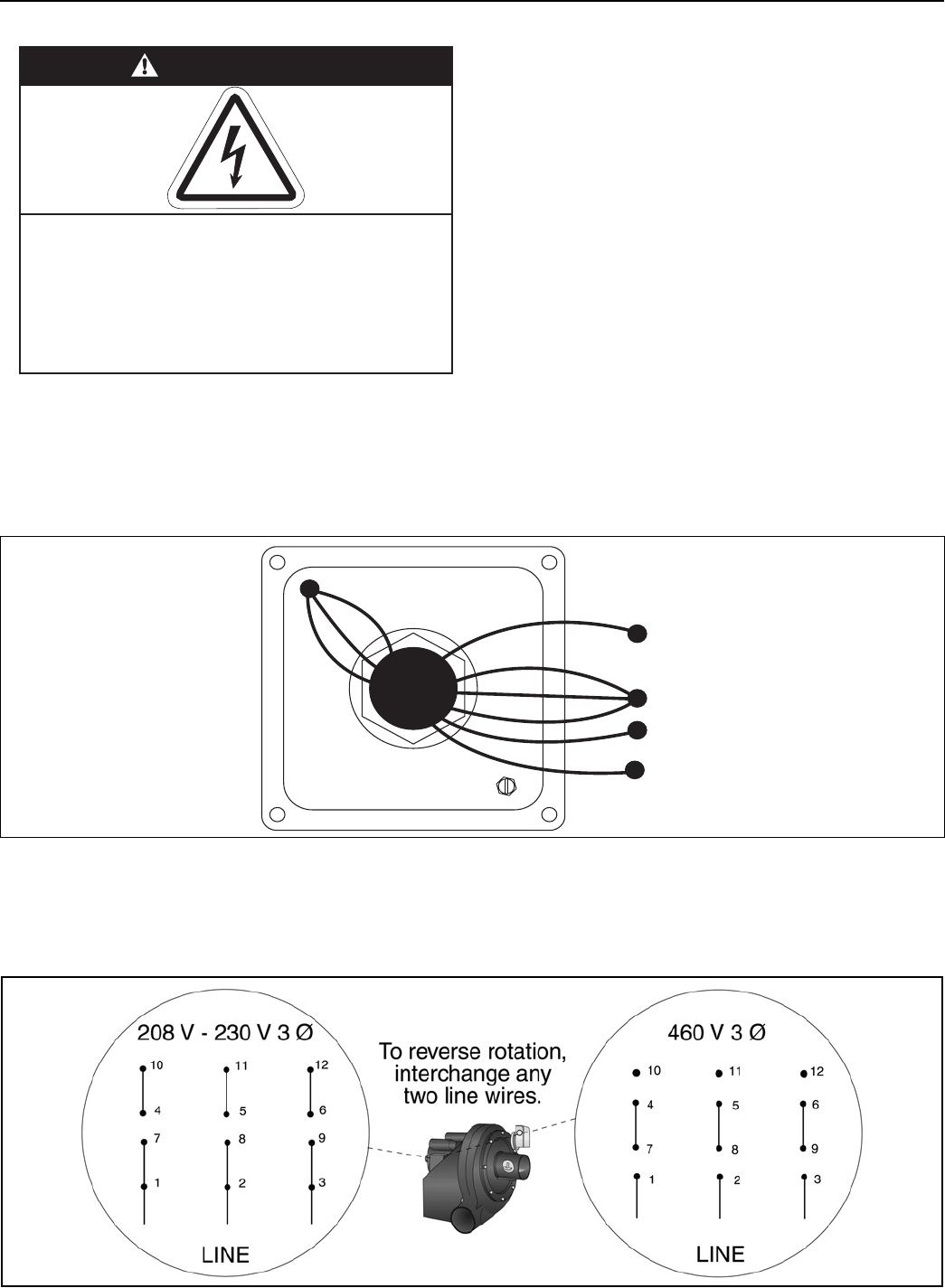
The EP-203 motor can be wired for 3 Ø, 208 V - 230 V, 60 Hz or 3 Ø, 460 V, 60 Hz operation.
The EP-203 motor rotation direction can be changed by interchanging any two leads.
Wire the pressure switch per the CORAYVAC
®
(P/N 127102NA), VANTAGE
®
EV (P/N 151100NA) or appropiate
controller installation manual.
FIGURE 12: EP-203 Motor Wiring
WARNING
Electrical Shock Hazard
Disconnect electrical power and gas supply before
servicing.
This appliance must be connected
to a properly grounded electrical source.
Failure to follow these instructions can result in
death or electrical shock.
Ground
Screw
O
r
a
n
g
e
B
r
o
w
n
/
W
h
i
t
e
Y
e
l
l
o
w
/
B
l
a
c
k
B
l
a
c
k
Y
e
l
l
o
w
W
h
i
t
e
B
r
o
w
n
R
e
d
115V Power Supply
(Control Panel or Relay)
Motor Junction Box
B
r
o
w
n
/
W
h
i
t
e
Line
Motor
Interlock
(Not Used)
Neutral
EP-201 Motor
To reverse rotation,
interchange black
and red leads.