


CRV-SERIES DESIGN MANUAL
30
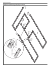
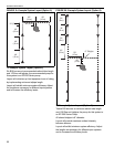
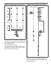
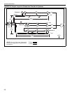
FIGURE 29: Sample Layout for Pressurized Outside Air Systems
*NOTE: up to 10' (3 m) max. from blower
inlet can be neglected for pressure drop
calculations.
4
4
4
10
20 8
8
8
110'
(33 m)
(44)
15 6
66
(22)
(33)
P
100'
(30 m)
15'
(4.5 m)
B
50'
(15 m)
10'
(3 m)
max.*
4" duct
4" duct
Branch A
Branch B
Walls
Branch C
4" duct
6" Duct
4" Duct
6" duct