


CRV-SERIES DESIGN MANUAL
14
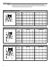
5.2 Pump Capacity
The flow unit capacity of the pump is indicated on
Page 14, Table 2, as a function of installed altitude.
When the CRV-Series system is designed in accor-
dance with this set of instructions and is in proper
operating condition, a vacuum from 2-3" w.c. will be
obtainable at each end vent (i.e. at all burners).
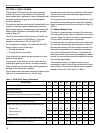
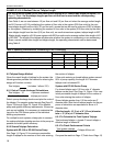
Table 2: Pump Capacity
There are a number of design requirements which, if
not met, will reduce the vacuum obtainable and
thereby the effective flow capacity of the pump. These
include:
• Minimum Length of Tailpipe - If less than the
minimum length of tailpipe is provided per radiant
branch, there will be insufficient cooling of the com-
bustion gases and improper operation of the pump.
• Line Loss Check for Tailpipe is applicable to
sections of tailpipe which are common to two or
more radiant branches (i.e. shared lengths). See
Page 14, Figure 15.
• Excessive back pressure on discharge line of
pump can be caused by partial blockage or too
much flow for length. See Section 5.3.1
• More than maximum number of burners or flow
units per radiant branch. See Page 14, Table 2.
• Excessive number of elbow or tee fittings
which increases vacuum loss.
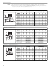
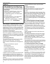
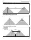
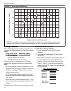
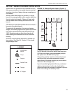
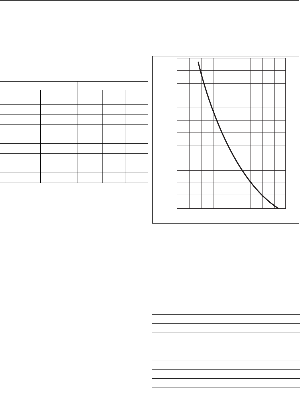
5.3 Tailpipe Flow
Excessive flow loading in a single section of tailpipe
can cause low vacuum and lower effective pump
capacity. For the pump to develop the proper vacuum,
the length of tailpipe m
ust not be excessive for the
number of flow units carried in the tube.
See Figure 15. Readings for length and flow when
plotted on the graph must fall on OK side to avoid
excessive vacuum losses.
FIGURE 15: Vacuum Loss Curve for 4" Shared
Tailpipe
NOTE: For 6" (15 m) tailpipe, length is limited to a
maximum of 100’ (30 m). See Page 16, Section 6.3
for more details.
Lengths shown include allowance for 1 elbow every
50' (15 m); deduct 15% of length for each additional
elbow used per 50' (15 m) length.
5.3.1 Pump Exhaust Length Requirements
The tube length on the exhaust side of the pump is
considered excessive if not within the following condi-
tions:
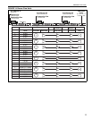
Table 3: Pump Exhaust Requirements
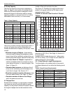
Installed Altitude Maximum Flow Units
Feet Above
Sea Level
Meters Above
Sea Level
EP-100
EP-200
Series
EP-300
Series
0
' - 2000'
0 m - 609 m 66 112 224
2001' - 3000'
610 m - 914 m 63 105 215
3001' - 4000'
915 m - 1219 m 60 100 206
4001
' - 5000'
1220 m - 1524 m 57 95 197
5001' - 6000'
1525 m - 1828 m 54 90 188
6001' - 7000'
1829 m - 2134 m 51 84 180
7001
' - 8000'
2135 m - 2438 m 48 80 170
8001' - 9000'
2439 m - 2743 m 45 75 161
Pump Series Exhaust Tube Length Exhaust Tube Diameter
EP-100 Up to 25' (7.6 m) 4" 3 Elbows
EP-100 Up to 50' (15 m) 5" 3 Elbows
EP-200 Up to 10' (3 m) 4" 0 Elbows
EP-200 Up to 25' (7.6 m) 5" 3 Elbows
EP-200 Up to 50' (15 m) 6" 3 Elbows
EP-300 Up to 10' (3 m) 6" 1 Elbows
EP-300 Up to 25' (7.6 m) 7" 3 Elbows
EP-300 Up to 50' (15 m) 8" 3 Elbows
NOT OK
OK
SIDE
10
20
30
40
50
60
70
80
90
100
120
130
Length of Tailpipe Section (feet)*
Maximum Flow Units per Single Tailpipe Section
30
40
50 60 70
80
90 100
110
120