


CRV-SERIES DESIGN MANUAL
24
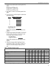
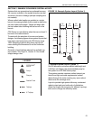
Layout to provide minimum system efficiency. Adjust
the lengths as necessary for different input systems
and to increase the efficiency levels.
This system is generally accompanied by an addi-
tional system, as shown, so that the radiant output of
the additional system supplements the lack of radiant
intensity from the tailpipe of the first system. This lay-
out method is used in high heatloss and perimeter
heating applications.
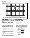
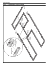
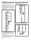
FIGURE 23: Example System Layout (Option 6)
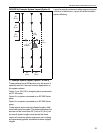
7.6 Example System Layout (Option 6)
Six B10 burners at minimum radiant tube length and
2.3'/flow unit tailpipe, the pump for this system is an
EP-200 Series pump.
Layout to provide high system efficiency, condensed
radiant output and good uniformity of distribution.
Adjust the lengths as necessary for different input sys-
tems and to change the efficiency levels.
This layout method is often used effectively in heatloss
and perimeter heating applications.
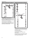
FIGURE 24: Example System Layout (Option 7)
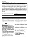
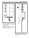
FIGURE 25: Example System Layout (Option 8)
100'
(30 m)
10' (3 m)
30'
(9 m)
30'
(9 m)
30'
(9 m)
10' (3 m)
30'
(9 m)
30'
(9 m)
30'
(9 m)
30'
(9 m)
30'
(9 m)
30'
(9 m)
negligible
180'
(55 m)
10' (3 m)
30'
(9 m)
30'
(9 m)
30'
(9 m)
10' (3 m)