


CRV-SERIES INSTALLATION, OPERATION AND SERVICE MANUAL
46
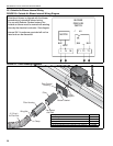
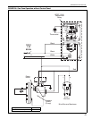
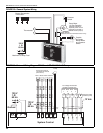
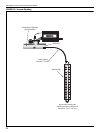
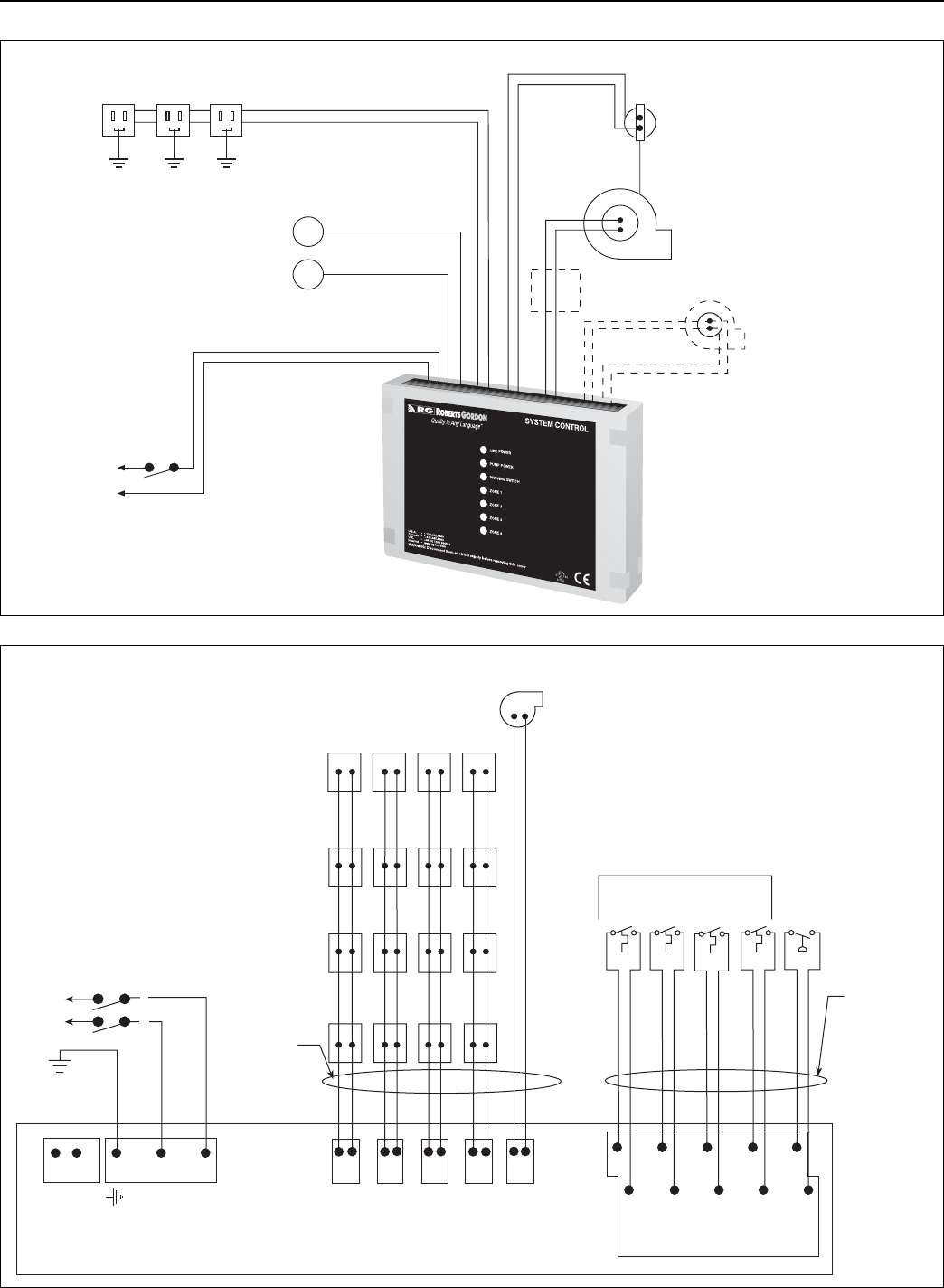
FIGURE 29: General System Wiring
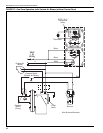
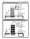
FIGURE 30: External Wiring Diagram EP-100 and EP-201 120 V 1 Ø Pump
Burner Receptacles
4 Zone Max
120 Vac
Maximum 20 Amps Total
Thermostats
Outside
Air Supply
Blower Motor
and Pressure
Switch
Pump Motor
115 Vac Operation
(230 Vac Operation-
separate power circuit
required for EP-203 or
EP-300 series pumps)
Pressure
Switch
Motor Starter
(Needed for EP-203 and EP-300 Series Pump)
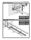
L
120 V
1 Ø
60 Hz
N
System Control
C
T1
C
C
C
C
T3
T2
T4
PS
12 Vdc
120 V
1 Ø
60 Hz
Ground
G
L
N
Ground
120 V
1 Ø
60 Hz
PUMP
NL
Z1
Z2
Z3 Z4
NN
N
NLL
L
L
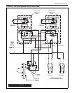
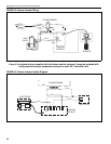
All burners must be
connected to Ground
(Not shown)
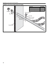
Zone 1
Zone 2 Zone 3 Zone 4
Pump
L
N
Low voltage thermostats
located in heated zone
Zone
1
Zone
2
Zone
4
Zone
3
Pressure switch
located at pump