


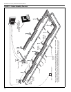
SECTION 7: HEATER I NSTALLATION
17
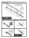
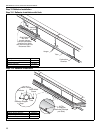
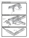
Step 7.2.1 Coupling and Tube Assembly (Continued)
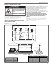
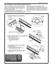
7.3 Elbow Package Configuration
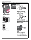
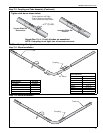
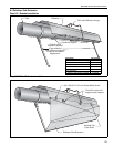
Step 7.3.1 Elbow Installation
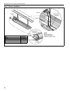
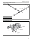
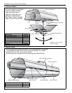
Step 7.3.2 Elbow Installation
Incorrect Slide Bar
Position
Correct Slide Bar
Dimensions
± 2" (5 cm)
Drive slide bar until tight.
End of slide bar should be
within tolerance listed below.
Repeat Step 7.2, A - D until all tubes are assembled.
NOTE: If coupling is not tight, loss of vacuum can occur.
Tighten slide bar as shown below.
Tube
90° Elbow
Coupling
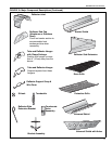
Description Part Number
Elbow Package 02718702
90° Elbow 01335801
Coupling 01312700
Reflector End Cap 02750800
Reflector Joint Piece 02750900
U-Clip Package 91107720
Minimum Distance Required Between
Burner and Elbow
Model Minimum Distance
CRVB-2 5' (1.5 m)
CRVB-4 5' (1.5 m)
CRVB-6 10' (3 m)
CRVB-8 10' (3 m)
CRVB-9 10' (3 m)
CRVB-10 15' (4.5 m)
CRVB-12A 15' (4.5 m)
CRVB-12 15' (4.5 m)
Tube
Coupling