


CRV-SERIES INSTALLATION, OPERATION AND SERVICE MANUAL
42
SECTION 12: CONTROL METHODS
There are several methods of controlling CRV-Series
systems. The options are as follows:
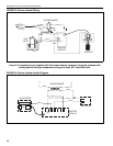
12.1 ROBERTS GORDON
®
System Control
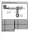
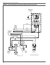
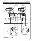
The System Control is an electronic control panel
designed to control CRV-Series heating systems.
The System Control wiring is shown on Page 46,
Figure 29 through Page 47, Figure 32 and in the
System Control Installation Manual
(P/N 10091601NA). The System Control can be used
to control an EP-100 or EP-201 pump from the control
panel. Other pumps such as the EP-301 and 3 phase
models may be controlled by a relay or motor starter.
The System Control can control up to four zones of
burners.
The electrical circuit is a 120V AC (20A) supply.
The output for the thermostat is 12V DC. Do not use
thermostats that draw power from the low voltage
supply.
A System Control operated system has two minutes
post purge pump operation to completely exhaust
products of combustion from the system. A system
control provides indication of power to the pump and
the zones as well as indicating the status of the
pressure switch with lights.
The System Control is UL listed in accordance with
UL873 – Temperature Indicating and Regulating
Equipment.
12.2 ROBERTS GORDON
®
ULTRAVAC
TM
The ROBERTS GORDON
®
ULTRAVAC
TM
is a micro
processor based control package designed for
modulating control of CRV-Series heaters based on
outdoor temperatures. The controls offer full
modulation between 60% and 100% of system
maximum rated input.
This controller is capable of giving control outputs to
one pump and three heating zones. The controller
also features inputs which are used for indoor and
outdoor signal condition monitoring.
System status and settings are viewed and altered
from a PC (not supplied) running ROBERTS
GORDON
®
ULTRAVAC
TM
Software.
ROBERTS GORDON
®
ULTRAVAC
TM
Software
requires a PC (not supplied) running Windows
®
95 or
higher, with a Pentium
®
class processor and at least
64k of RAM.
Special design requirements apply for CRV-
Series systems using the ROBERTS GORDON
®
ULTRAVAC
TM
Controller.
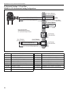
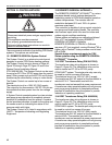
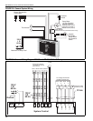
12.3 SPST Transformer Relay (P/N 90417600)
The transformer relay wiring diagram is shown on
Page 43, Figure 26. The transformer relay can be
used to control an EP-100 or EP-201 pump
CORAYVAC
®
system. The single pole relay can only
be used to control one zone of burners.
The electrical circuit is a 120V AC (20 A) supply.
The transformer 24V AC output for the thermostat is
rated at 40 V A. Thermostats used with the
transformer must not exceed this power requirement.
A transformer relay operated system will not give any
post purge pump operation to completely exhaust
products of combustion from the system or provide
indication of operating conditions.
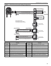
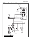
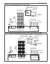
12.4 DPST Transformer Relay (P/N 90436300)
The transformer relay wiring diagram is shown on
Page 45, Figure 28. The transformer relay can be
used to control an EP-100 or EP-201 pump
CORAYVAC
®
system. The double pole relay can only
be used to control two zones of burners.
The electrical circuit is a 120V AC (20A) supply.
The transformer 24V AC output for the thermostat is
rated at 40VA. Thermostats used with the
transformer must not exceed this power requirement.
A transformer relay operated system will not give any
post purge pump operation to completely exhaust
products of combustion from the system or provide
indication of operating conditions.
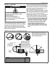
WARNING
Electrical Shock Hazard
Disconnect electrical power and gas supply before
servicing.
This appliance must be connected
to a properly grounded electrical source.
Failure to follow these instructions can result in
death or electrical shock.