


SECTION 9: PUMP INSTALLATION AND VENTING
31
SECTION 9: PUMP INSTALLATION AND VENTING
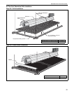
9.1 Pump Installation
For complete pump installation, please refer to the EP-100, EP-200 or EP-300 Series Installation,
Operation and Service Manuals.
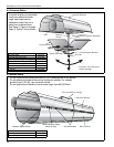
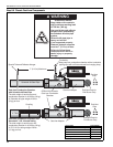
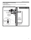
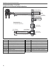
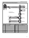
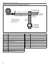
FIGURE 14: EP-200 Condensate Valve Assembly
Wall
1" NPT threaded hole.
Use 1" x ¾" reducer.
(not supplied)
Must be connected
to a drain system
in accordance with
local codes.
flow
Condensate
Valve
Assembly
3/4" female
3/4" female
36" (.9 m)
Minimum
vertical drop
between pump
and condensate
valve assembly.
Copper or
galvanized pipe
between pump
and condensate
valve.
Description Part Number
Condensate Valve Assembly 01327001