


CRV-SERIES INSTALLATION, OPERATION AND SERVICE MANUAL
8
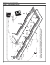
SECTION 5: MAJOR COMPONENTS
The figures in this section provide a general overview
of component placement in a CRV-Series system.
The location of some components such as supports
and couplings is crucial for proper installation.
Assemble the heater components as shown on Page
14, Figure 11.
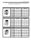
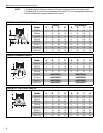
Optional reflector configurations are shown on Page
4, Figure 1 through Page 6, Figure 9. Install
appropriate suspension hardware, beam clamps,
chain or rod at predetermined locations. Adjustments
of chain length will provide uniform pitch.
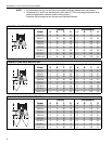
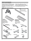
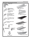
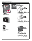
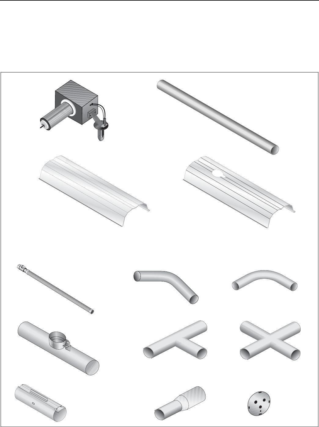
FIGURE 10: Major Component Descriptions
Burner
Tube
Hot rolled, heat treated or
coated aluminized tube
supplied in 10' (3 m) lengths.
45° Elbow
90° Elbow
End Vent
Coupling Assembly
with Lock
Flex Gas Line
with shut-off cock
Combustion Chamber
Tee
Reflector
(Aluminum or
Stainless Steel)
Alternate overlap as
shown on overview.
Minimum overlap is 6"
(16 cm).
Reflector with Hole
(Aluminum or
Stainless Steel)
Alternate overlap as
shown on overview.
Minimum overlap is 6"
(16 cm).
Tube Adapter
Cross