


CGTH INSTALLATION, OPERATION AND SERVICE MANUAL
22
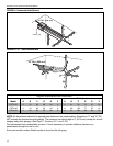
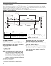
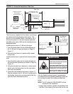
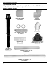
5.3 Galvanized Horizontal Venting
After the heater has been properly suspended in
accordance with the preceding headings of this sec-
tion, proceed to install the venting as described
below (See Page 23, Figure 16):
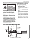
1. Using a tape measure, measure the distance from
the floor to the center of the vent collar on the rear
surface of the burner. Note this dimension here
__________.
2. Using the tape measure, transfer this measure-
ment to the inside surface of the exterior wall that
the vent will penetrate; make a reference mark.
Check the location of the hole to ensure that there
are no internal wall structures (i.e. studs) to pre-
vent penetration. Also check that the outlet of the
vent does not compromise the general venting
requirements, See Section 5.1.
3. Using the tape measure, measure the distance
between the rear surface of the heater and the
exterior wall. Note this dimension here _________.
NOTE: If the distance between the rear surface of
heater and the exterior wall is greater than 5'
(1.5 m), a 5’ (1.5 m) balanced flue vent exten-
sion kit (P/N 08039000) will be required.
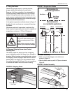
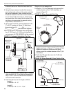
4. From the reference mark made in step 2, measure
down vertically 1/4" (6 mm) per foot measured in
step 3. Cut 5” (125 mm) vent terminal clearance
hole at the lower reference.
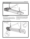
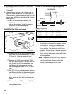
5. Install 3" (80 mm) flue pipe from the vent collar, on
the rear surface of the burner, and through the
exterior wall. Be sure to seal any joints in the 3" (80
mm) flue pipe with high temperature silicone seal-
ant and secure them with three sheetmetal screws.
IMPORTANT: The 3" (80 mm) flue pipe must extend
a minimum of 6" (150 mm) beyond the
exterior surface of wall/fresh air intake.
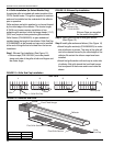
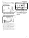
6. Assemble or cut the 5" (125 mm) air supply pipe to
run between the vent collar on the rear surface of
the burner and the outside surface of the exterior
wall. Be sure to seal any joints in the 5" (125 mm)
air supply pipe with high temperature silicone seal-
ant and secure them with three sheetmetal screws.
7. From the exterior of the building, slip the assem-
bled or cut 5" (125 mm) air supply pipe over the
installed 3" (80 mm) flue pipe. Connect the 5" (125
mm) pipe to the vent collar on the rear surface of
the burner with high temperature silicone sealant
and secure the connection with three sheetmetal
screws.
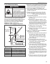
8. From the exterior of the building, slip the vent ter-
minal onto the 3" (80 mm) flue pipe and guide the
sleeve portion of the vent terminal over the 5" (125
mm) air supply pipe that is flush with exterior sur-
face of wall. Secure air vent pipe to the vent termi-
nal collar with silicone sealant.
9. Secure the vent terminal to the exterior surface of
the wall.
NOTE: If the protruding 3" (80 mm) flue pipe is
directly below and within 24" (609 mm) of the
building soffit, the optional vent extension
should be used.
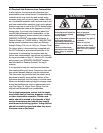
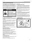
Carbon Monoxide Hazard
Heater must be exhausted outside.
Use materials supplied.
This heater needs fresh air for safe
operation and must be installed so
there are provisions for adequate
combustion and ventilation air.
Failure to follow these instructions
can result in death or injury.
WARNING