


SECTION 2: INTRODUCTION
7
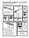
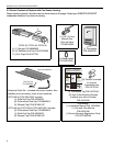
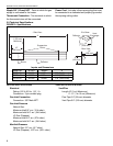
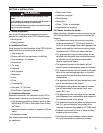
2.8 Components Identification
FIGURE 1: Components Identification
Burner - Contains the electrical components (i.e.
blower motor, power transformer, etc.) and gas distri-
bution components (i.e. gas valve, etc.) that make
the heater work. There are no owner serviceable
items contained in this box.
Front Fixed Hanger - Provides rigid support and
mounting surface for the reflector. Holes are provided
in the upper corners of the bulkhead to accommo-
date suspension hardware required for installation of
the heater.
Reflector - The reflector is made from formed alumi-
num and reflects the radiant energy downward to the
space to be heated.
Heat Exchanger - A U-shaped tube through which
the heated products of combustion pass.
Rear Movable Hanger - Provides support for the tube
and reflector at the end that is furthest from the burner.
The support may be moved (within limits) to accom-
modate hanging of the unit.
Service Door - To be removed only by a contractor
qualified in the installation and service of gas-fired
heating equipment or your gas supplier. Removal of
this service door provides access to the electrical
and gas distribution components.
Gas Line - Must only be installed and serviced by a
licensed contractor or gas fitter.
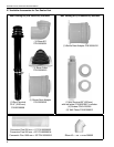
Wall Termination Plate - Placed on the outside wall
over the venting.
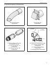
Venting - Installer must properly exhaust the heater
outside. The 5” outer duct carries fresh air to the
burner. The 3” inner duct carries the products of com-
bustion to the outside.
Thermostat - 24 Volt Thermostat mounted with
Safety Tag.
Protective Grille - Included with select models. See
Page 20, Section 4.14 for details.
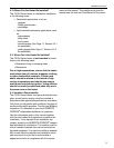
Vent Collar - Accommodates a 5" (125 mm) diame-
ter combustion air inlet duct that delivers fresh air to
the burner. The fresh air enters the burner through
the twelve equally spaced holes shown above. The
3" (80 mm) diameter hole in the center of the flue col-
lar accommodates the venting duct that carries the
products of combustion to be vented outdoors.
Reflector
Heat Exchanger
Burner
Front Fixed Hanger
Rear Movable
Hanger
Service Door
Venting
Wall Termination Plate
Gas Line
Protective Grill
Manual Gas
Shut-off Valve
Thermostat
Connection
Power
Cord
Nipple 3/8
(10 mm) NPT
Vent Collar
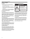
Fire Hazard
Some objects will catch fire or
explode when placed close to
heater.
Keep all flammable objects,
liquids and vapors the required
safe distances away from heater.
Keep children, clothing and
furniture away from the heater.
Failure to follow these
instructions will result in death,
injury or property damage.
WARNING
Printed in U.S.A./Imprimé aux Etats-Unis
This thermostat controls your overhead tube heater. Keep burner, control compartment and reflector clean. Read
your CGTH-Series Use and Care Manual (P/N 180101NA or GH80101NA) and follow all Safety Requirements which
include checking your heater monthly. Installation, Service and Annual Inspection must be done by a contractor
qualified in the installation and service of gas-fired heating equipment. Please call (716) 852-4400 (USA) or (905)
945-5403 (Canada) if you need a manual or have questions.
Ce thermostat commande votre radiateur. Gardez le module de contrôle et le reflécteur propres. Lisez le manuel
dutilisation et dentretien CGTH-Series (P/N 180101NA ou GH80101NA) et respectez tous les conseils de sécurité,
notamment le contrôle mensuel du radiateur. Linstallation, l'entretien et linspection annuelle doivent être effectués
par un agent agréé. Veuillez nous contactez au 716-852-4400 (USA) ou au 905-945-5403 (Canada) pour toutes
questions ou demandes de manuel.
MOUNT
THERMOSTAT
HERE
MONTER LE
THERMOSTAT ICI
ATTENTION
Risque d'incendie
Certains objets placés près du
radiateur peuvent s'enflammer ou
exploser.
Tenir tous les objets, iquides et
vapeurs inflammables à la
distance de sécurité requise du
radiateur.
Surveiffer les enfants. Gardes les
vêtements, les meubles loin de
l'appareil.
Le non-respect de ces consignes
peut causer dommage au matériel.
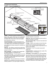
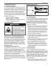
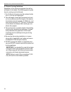
Required Safe Distances from Combustibles
Distances de Dégagement par Rapport aux Combustibles
Horizontal Mount
Montage Horizontal
45° Mount
Montage à 45°
24" Min. (
61 cm)
A
A
D
D
E
E
A
A
F
F
App
ro
x.
45
°
F
B
A
C
24" Min. (61 cm)
B
Rating Tag
Éttiquette de
Classement
by
CGTH-Series
®
NOTES:1. Toutes les dimensions sont mesurées à partir du réflecteur.
2. Les chiffres noirs sont en pouces. Les chiffres oranges
sont en centimètres.
3. Vous devrez connaître le numéro de votre modèle. Il se
trouve sur létiquette de classement. (Voir le dessin du
montage horizontal pour lemplacement de létiquette de
classement).
Model A B C D E F
CGTH-30 4 16 36 28 34 6
CGTH-40 4 18 48 30 34 6
CGTH-50 4 20 48 32 36 6
Modèle A B C D E F
CGTH-30 11 41 92 72 87 16
CGTH-401146122 77 8716
CGTH-50 11 5112282 92 16
©
www.rg-inc.com
P/N 91037903 Rev F
NOTES:1.All dimensions are from the reflector.
2. Black numerals are in inches.
Orange numerals are in
centimeters.
3. Know your model number. Model number is found on the
rating tag. (See horizontal mount drawing for location of
rating tag).