


SECTION 15: SPECIFICATIONS
37
SECTION 15: SPECIFICATIONS
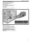
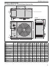
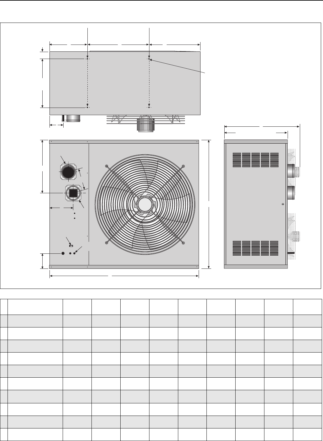
15.1 Standard (Models 150 - 400) UHA(S) Series Dimension Data
A
B
Rear View
End View
Z
25 1/2" (65 cm)
6 1/2"
(17 cm)
Gas
Supply
F
G
H
Top View
I
E
C
D
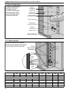
77
Heater must be supported
at these points from above
or below.
19 3/8"
(49 cm)
Support
Centers
4 x 3/8" Captive Nuts Provided
Lockout Reset
Electrical
Cable Entry
Air Intake
(UHAS only)
Flue
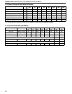
Model
UHA[S]
150
UHA[S]]
175
UHA[S]
200
UHA[S]
225
UHA[S]
250
UHA[S]
300
UHA[S]
350
UHA[S]
400
A
Width
in
(cm)
42.4
(108)
42.4
(108)
42.4
(108)
42.4
(108)
42.4
(108)
52.3
(133)
52.3
(133)
52.3
(133)
B
Height
in
(cm)
26.9
(68)
26.9
(68)
35.2
(89)
35.2
(89)
35.2
(89)
43.5
(110)
43.5
(110)
43.5
(110)
C
Support Spacing
in
(cm)
17.7
(45)
17.7
(45)
17.7
(45)
17.7
(45)
17.7
(45)
24.7
(63)
24.7
(63)
24.7
(63)
D
Support Spacing
in
(cm)
12.3
(31)
12.3
(31)
12.3
(31)
12.3
(31)
12.3
(31)
12.3
(31)
12.3
(31)
12.3
(31)
E
Support Spacing
in
(cm)
12.4
(32)
12.4
(32)
12.4
(32)
12.4
(32)
12.4
(32)
15.3
(39)
15.3
(39)
15.3
(39)
F
Centre of Flue
in
(cm)
15.5
(39)
15.5
(39)
17.5
(44)
17.5
(44)
17.5
(44)
13.8
(35)
13.8
(35)
13.8
(35)
G
Centre of
Flue/Air Intake
in
(cm)
5.5
(14)
5.5
(14)
6.4
(16)
6.4
(16)
6.4
(16)
7
(18)
7
(18)
7
(18)
H
Position of Flue
in
(cm)
8.2
(21)
8.2
(21)
8.8
(22)
8.8
(22)
8.8
(22)
11
(28)
11
(28)
11
(28)
I
Gas Inlet Position
in
(cm)
5.8
(15)
5.8
(15)
5.8
(15)
5.8
(15)
5.8
(15)
5.8
(15)
5.8
(15)
5.8
(15)
Z
Length
in
(cm)
34
(86)
34
(86)
34
(86)
34
(86)
34
(86)
34
(86)
34
(86)
34
(86)