


COMBAT
®
UHA UNIT HEATER INSTALLATION OPERATION AND SERVICE MANUAL
32
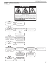
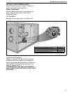
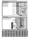
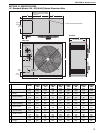
14.2 Burner Compartment
Remove flexible
air duct from spigot
Remove
access plate
Remove screws and
pull off burner cover
Viewing port
for flame probe
Viewing port
for ignition electrode
Flame probe
Burner
compartment
cover
Rubber Seal
Ignition electrode
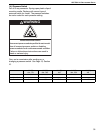
The burner compartment is
a sealed compartment.
Following any work,
re-seal the compartment
with the gas pipe rubber
seal fully in place and all
screws fitted and tight.
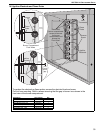
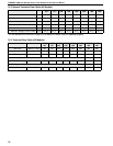
14.2.1
Remove manifold
screws and pull
out manifold
Manifold
Burners
Injectors
Burner
Screws
Burner
venturi
Unscrew
Injectors
Manifold
Marking
Folded
Hem
Ensure gas tight fitting of injectors.
Ensure correct alignment with burners.
Ensure all pipe joints are gas tight.
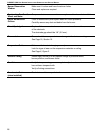
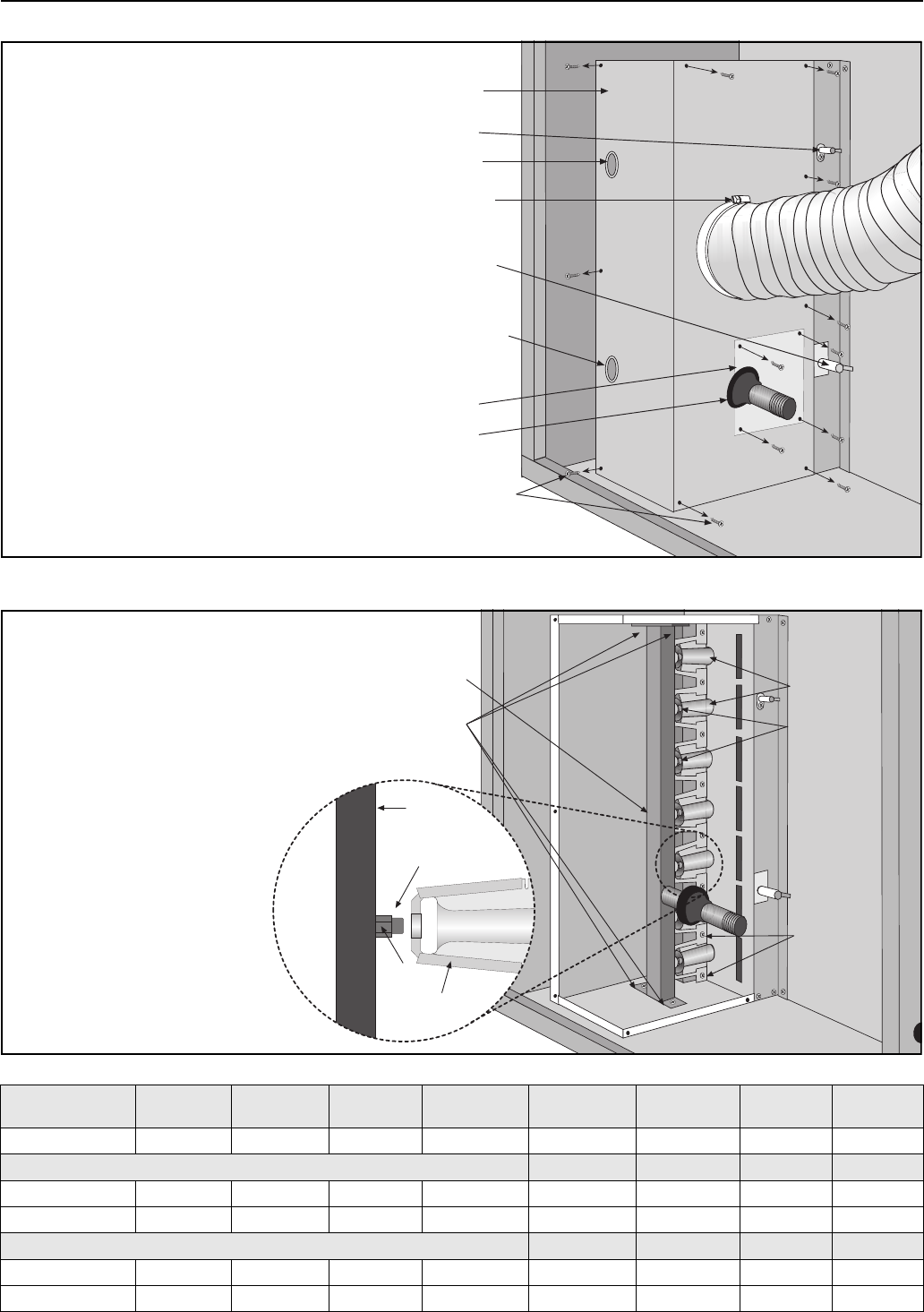
Burner Injectors
MODEL
UHA[S]
150
UHA[S]
175
UHA[S]
200
UHA[S]
225
UHA[S]
250
UHA[S]
300
UHA[S]
350
UHA[S]
400
Orifice Quantity 7 8 9 10 11 12 14 14
Natural Gas (G20)
Orifice Marking 43 43 2.25 mm 2.25 mm 2.25 mm 40 40 40
RG P/N 91930043 91930043 91930225 91930225 91930225 91930040 91930040 91930040
Propane (G31)
Orifice Marking 1.35 mm 1.35 mm 54 54 54 1.45 mm 53 53
RG P/N 91930135 91930135 91930054 91930054 91930054 91930145 91930053 91930053