


COMBAT
®
UHA UNIT HEATER INSTALLATION OPERATION AND SERVICE MANUAL
36
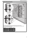
14.6 Ignition Control
The control mounts to the electrical plate. Pull out
ignition cable and wiring from board, noting their
positions.
Release the four mounting standoffs.
Refit in reverse. Ensure correct location of ignition
cable and all other wiring.
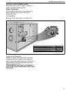
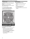
14.7 Axial Fan/Guard/Motor Assembly
The axial fan unit for the heater is supplied
completely assembled and balanced.
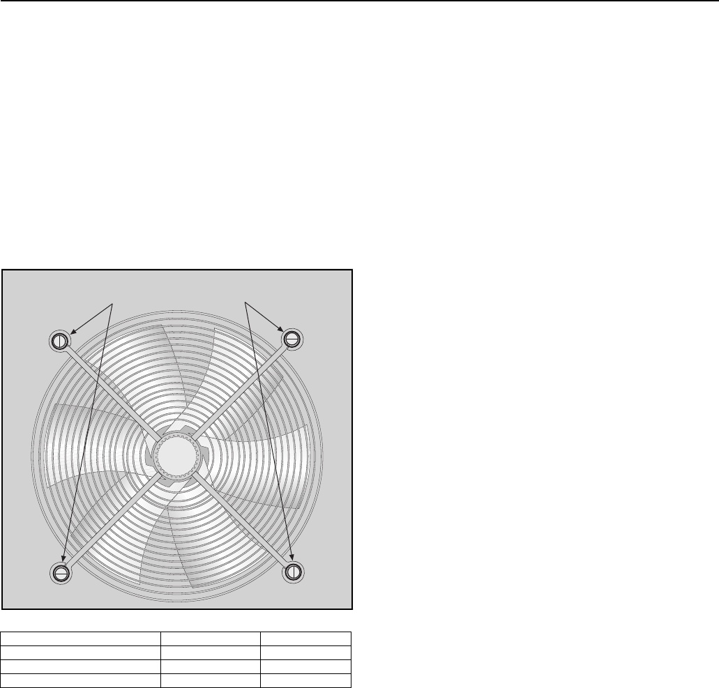
14.7.1 Fan Removal
Remove the screws
and washers.
Remove the mounting hardware.
and Replacement
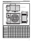
Description Part Number Qty.
Axial Fan UHA[S] 150 - 175 90710416 1
Axial Fan UHA[S] 200 - 250 90710417 1
Axial Fan UHA[S] 300 - 400 90710416 2
14.7.2 To Replace the Fan Assembly
To replace the fan assembly, reverse the procedure
shown above.
• Check that the fan blades are free to rotate
before turning on the power to the fan.
• Strictly comply with the color code of the fan
wires to ensure correct operation.
See Page 16,
Section 9.3 wiring diagram.
• Use only genuine ROBERTS GORDON
®
replacement parts.
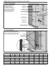
14.8 Limit Switches
14.8.1 Removal and Replacement
1. Remove the electrical connections to the
switch.
2. Unscrew the two screws securing the
switch.
3. Fit a new switch with two screws.
See Page 38, Section 15.3.
4. Reconnect the electrical connections and test
operation.