


PG 10
PG 9
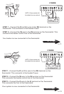
RH
G
Y
W
C
From
Fu
r
n
ace
And
AC unit
R
or
RC
G
Y
W
C
From
Fu
r
n
ace
And
AC unit
RH
Go To Page 13
Go To Page 14
Go To Page 12
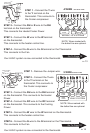
RH
W
C
From
Fu
r
n
ace
G
Go To Page 17
Go To Page 15
Go To Page 16
W
RH
R
or
From
Fu
r
n
ace
Go To Page 11
C
or R
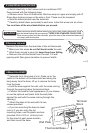
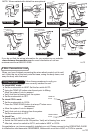
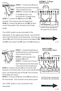
9 Wire Connections cont
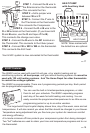
When you have finished connecting the wires attach control unit to wall
unit. Hook the top of the body onto the base, swing the body down, and
snap the body onto the base.
C
RC
W
2
O
B
RH
W
Y
G
H
EA
T
C
O
O
L
AU
T
O
O
N
O
F
F
F
A
N
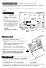
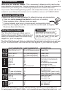
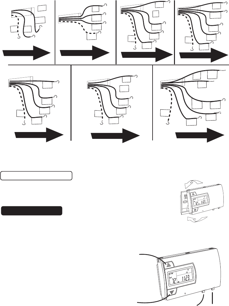
10 Check Unit
Follow these procedures to verify you
have correctly installed the unit.
To check HEAT mode:
.
Set the mode switch to HEAT. Set the fan switch AUTO.
.
Using the TEMP UP button raise the set point to 90deg.
.
Allow the system 5 min to respond.
.
Verify that heat is blowing from the system.
.
Set the mode switch to OFF.
To check COOL mode:
.
Set the mode switch to COOL.
.
Press the TEMP DOWN button to a temp 5
o
below room
temperature.
.
Allow the system 5 min to respond.
.
Verify that cool air is blowing from the system.
.
Set the mode switch to OFF.
To check Fan:
.
Switch mode to OFF during fan test.
.
Switch the FAN switch to the ON position. Verify air is blowing from vents.
.
After test, return fan switch to AUTO, and mode to HEAT or COOL.
Congratulations, you have successfully installed your unit. Please proceed to the OPERATING GUIDE
to initialize the new thermostat. REMEMBER, Mode switch must be in HEAT or COOL to operate.
H
E
A
T
CO
O
L
A
U
T
O
O
N
O
F
F
FA
N
If you do not find the wiring information for your system try our website:
www.ritetemp-thermostats.com for more information or call our
customer service at 888-515-2585.
W
G
W2
R
C
Fr
om
Normal
two stage s
ystem
B
G
Y
R
C
From hea
t
pu
mp
with ou
t
Aux he
at
O
or
B
G
Y
R
C
Fr
om
heat pump
with
Aux heat
O or
W or W2
TEMP UP
arrow
Mode Switch
Fan Switch
TEMP DOWN
arrow
NOTE: Wires marked with dotted line are optional.