


PG
8
PG
7
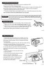
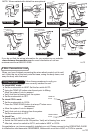
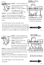
Please refer back to these guidelines for safe and secure wire connections.
.
Take care not to damage the labels for each wire in handling.
.
Strip insulation 3/8 in. (9.5mm) from wire ends.
.
Connect labeled wires only to a terminal with corresponding letter.
.
Bend the wire slightly, insert the wire under the contact plate and tighten
the screw down onto the wire.
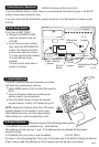
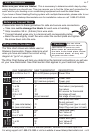
The Wire chart shows wire labels used on
Ritetemp thermostats. Please determine what
wires you have and select the correct wiring
diagram to "go to" on pages 9.
Before you Connect Wires
What Wires Do You Have?
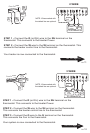
9 Wire Connections
Make sure your wires are labeled. This is necessary to determine which step-by-step
wiring diagram you should use. This may require you to find the 'other end' connection for
each wire on your heating or air conditioning equipment and read the label there.
If you have a Zoned Heating/Cooling system with multiple thermostats, please refer to our
website at www.ritetemp-thermostats.com for installation notes or call 1-888-515-2585.
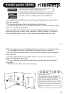
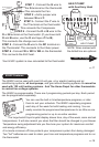
Caution
Do not allow
wires to touch
each other or parts on unit.
Wires must be routed through
the hole in the back plate, below
the terminal block, or they will
hit parts on the cover.
The Wire Chart below will help you determine the terminal connections you will use
on your new thermostat. See chart section that applies to your heat/cool system.
OLD THERMOSTAT NEW THERMOSTAT DESCRIPTION
R or RH or 4 or V RH or RC(leave jumper) Power Wire
RH or 4 or V RH (remove jumper) Power Heat
RC or R RC (remove jumper) Power cool
W or H W Heat return
Y or M Y Cool return (compressor)
G or F G Fan return
C or X C AC source for thermostat
W2 or H2 W2 2nd stage of heat
Y2 do not connect 2nd stage of cool (n/a)
W2 W2 Heat pump Aux heat
E Do not connect
O (see note below) O Dmpr/Chg-over (pwr in cool)
B (see note below) B Dmpr/Chg-over (pwr in heat)
5 or R RH Power wire (pwr)
4 or W W Turn Valve on
6 or Y or B A Turn Valve off
R RH Power wire (pwr)
Y or B W Turn Valve off
W A Turn Valve on
ONE
Power
Wire
TWO
Power
Wires
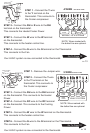
ZONED
MOTOR
VALVES
ZONED
SOLENOID
VALVES
HEAT
PUMPS
Note: On a heat pump, if O and B are both present, connect O to O and tape off B.
For wiring support call 1-888-515-2585 or visit our website at www.ritetemp-thermostats.com
Control wires